Service Manuals, User Guides, Schematic Diagrams or docs for : . Car Manuals Toyota Tundra 2000-2006 Approved 04-06 techinfo.toyota.com ileaf 06toyrm 06toypdf 06rmsrc 06tundra em2uzfe cylhea remo
<< Back | HomeMost service manuals and schematics are PDF files, so You will need Adobre Acrobat Reader to view : Acrobat Download Some of the files are DjVu format. Readers and resources available here : DjVu Resources
For the compressed files, most common are zip and rar. Please, extract files with Your favorite compression software ( WinZip, WinRAR ... ) before viewing. If a document has multiple parts, You should download all, before extracting.
Good luck. Repair on Your own risk. Make sure You know what You are doing.
Image preview - the first page of the document
>> Download remo documenatation <<
Text preview - extract from the document
EM-36
ENGINE MECHANICAL (2UZ-FE) - CYLINDER HEAD
EM1X0-02
REMOVAL
1. DRAIN ENGINE COOLANT
2. REMOVE THROTTLE BODY COVER
3. DISCONNECT TIMING BELT FROM CAMSHAFT TIM-
ING PULLEYS (See page EM-16)
NOTICE:
S Be careful not to drop anything inside the timing belt
cover.
S Do not allow the belt to come into correct with oil, wa-
ter or dust.
4. REMOVE CAMSHAFT TIMING PULLEYS
(See page EM-16)
5. REMOVE CAMSHAFT POSITION SENSOR
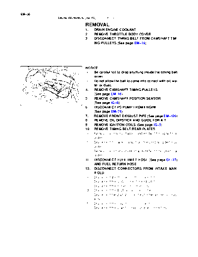
A02844 (See page IG-8)
6. DISCONNECT PS PUMP FROM ENGINE
(See page EM-79)
7. REMOVE FRONT EXHAUST PIPE (See page EM-126)
8. REMOVE OIL DIPSTICK AND GUIDE FOR A/T
9. REMOVE IGNITION COILS (See page IG-5)
10. REMOVE TIMING BELT REAR PLATES
(a) Remove the 3 bolts, stud bolt and RH No.1 timing belt rear
plates.
(b) Disconnect the wire clamp from the LH timing belt rear
plate.
(c) Remove the 3 bolts, stud bolt and LH No.1 timing belt rear
plates.
11. DISCONNECT FUEL INLET HOSE (See page SF-27)
AND FUEL RETURN HOSE
12. DISCONNECT CONNECTORS FROM INTAKE MAN-
IFOLD
(a) Disconnect the throttle control connector.
(b) Disconnect the VSV connector for EVAP.
(c) Disconnect the 8 injector connectors.
(d) Disconnect the ECT sensor connector.
(e) Disconnect the 2 VSV connectors for the air injection sys-
tem.
(f) Disconnect the 8 ignition coil connectors.
(g) Disconnect the 2 air fuel ratio sensor connectors.
EM-37
ENGINE MECHANICAL (2UZ-FE) - CYLINDER HEAD
13. DISCONNECT HOSES FROM INTAKE MANIFOLD
(d) (a) Disconnect the vacuum hose from the fuel pressure regu-
lator.
(b) Disconnect the PCV hose from the PCV valve on the LH
cylinder head.
(c) Disconnect the EVAP hose (from charcoal canister) from
the VSV for the EVAP.
(d) Disconnect the 2 vacuum hoses from the VSV for the air
injection system.
(a)
(c)
(b)
A23324
14. REMOVE INTAKE MANIFOLD ASSEMBLY
(a) Disconnect the 2 water bypass hoses from the throttle
body.
Water Bypass Hose A23325
(b) Disconnect the 2 wire clamps from the wire clamp bracket
on the RH delivery pipe.
A23326
(c) Remove the 2 bolts holding the engine wire protector from
the intake manifold and cylinder head.
(d) Remove the 2 bolts and ground cables from the RH and
LH cylinder heads.
(e) Remove the bolt and throttle body cover bracket from the
intake manifold.
A23327
EM-38
ENGINE MECHANICAL (2UZ-FE) - CYLINDER HEAD
(f) Disconnect the engine wire from the engine hanger and
wire bracket.
(g) Remove the wire bracket from the intake manifold.
A23328
(h) Remove the 6 bolts, 4 nuts, intake manifold assembly and
2 gaskets.
A23329
15. DISASSEMBLE INTAKE MANIFOLD
(a)
(a) (a) Remove the 2 bolts and VSVs for the air injection system.
(b) Disconnect the EVAP hose from the upper intake man-
(c) (b) ifold, and remove the VSV for EVAP.
(c) Remove the bolt, 2 unions, 4 gaskets and front fuel pipe
(c)
from the intake manifold.
(d) Remove the throttle body (see page SF-44).
(c)
A23330
(e) Remove the bolt and VSV for ACIS from the intake man-
ifold.
B17510
(f) Disconnect the fuel return hose from the fuel pressure
regulator.
(g) Remove the 3 bolts and fuel return pipe from the intake
manifold.
(h) Remove the 2 bolts, fuel pressure regulator and O-ring.
(i) Remove the fuel pressure pulsation damper and 2 gas-
kets.
(j) Remove the 2 delivery pipes and 8 injectors (see page
A23331 SF-27).
EM-39
ENGINE MECHANICAL (2UZ-FE) - CYLINDER HEAD
16. REMOVE WATER INLET AND INLET HOUSING AS-
SEMBLY (See page CO-6)
17. REMOVE AIR PUMP ASSEMBLY (See page EC-23)
18. REMOVE NO.2 AIR SWITCHING VALVES
(See page EC-23)
19. REMOVE FRONT WATER BYPASS JOINT
Front Water Bypass Joint Remove the 4 nuts, water bypass joint and 2 gaskets.
A23332
Rear Water Bypass Joint 20. REMOVE REAR WATER BYPASS JOINT
Remove the 4 nuts, water bypass joint and 2 gaskets.
21. REMOVE ENGINE HANGERS
A23333
22. REMOVE CYLINDER HEAD COVERS
Remove the 18 bolts, seal washers, RH and LH cylinder head
covers and 2 gaskets.
23. IF NECESSARY, REMOVE SEMI-CIRCULAR PLUGS
AND CAMSHAFT HOUSING PLUGS
24. REMOVE CAMSHAFTS
NOTICE:
Since the thrust clearance of the camshaft is small, the
A05564 camshaft must be kept level while it is being removed. If the
camshaft is not kept level, the portion of the cylinder head
receiving the shaft thrust may crack or be damaged, caus-
ing the camshaft to seize or break. To avoid this, the follow-
ing steps should be carried out.
EM-40
ENGINE MECHANICAL (2UZ-FE) - CYLINDER HEAD
(a) Check the crankshaft pulley position.
Check that the timing mark of the crankshaft pulley is
No.2 Idler
Pulley Bolt aligned with the centers of the crankshaft pulley bolt and
idler pulley bolt.
NOTICE:
Having the crankshaft pulley at the wrong angle can cause
Timing
Mark the piston head and valve head to come into contact with
Crankshaft each other when you remove the camshaft, causing dam-
Pulley Bolt
A04456 age. So always set the crankshaft pulley at the correct
angle.
Movement Oil Control Valve (b) Release the oil from the front bearing caps.
(25◦ Jabse Service Manual Search 2026 ◦ Jabse Pravopis ◦ onTap.bg ◦ Other service manual resources online : Fixya ◦ eServiceinfo