Service Manuals, User Guides, Schematic Diagrams or docs for : . Car Manuals Toyota Tundra 2000-2006 Approved 04-06 techinfo.toyota.com ileaf 06toyrm 06toypdf 06rmsrc 06tundra em2uzfe enguni4w remo
<< Back | HomeMost service manuals and schematics are PDF files, so You will need Adobre Acrobat Reader to view : Acrobat Download Some of the files are DjVu format. Readers and resources available here : DjVu Resources
For the compressed files, most common are zip and rar. Please, extract files with Your favorite compression software ( WinZip, WinRAR ... ) before viewing. If a document has multiple parts, You should download all, before extracting.
Good luck. Repair on Your own risk. Make sure You know what You are doing.
Image preview - the first page of the document
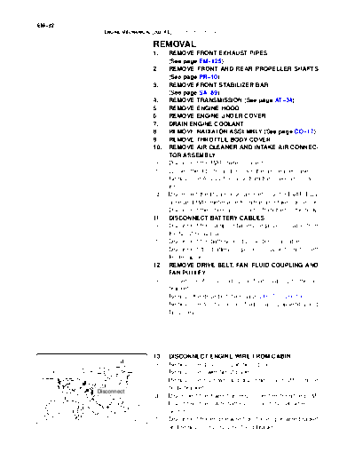
>> Download remo documenatation <<
Text preview - extract from the document
EM-92
          ENGINE MECHANICAL (2UZ-FE)   -   ENGINE UNIT (4WD)
                                                                                         EM11X-08


                              REMOVAL
                              1.    REMOVE FRONT EXHAUST PIPES
                                    (See page EM-125)
                              2.    REMOVE FRONT AND REAR PROPELLER SHAFTS
                                    (See page PR-10)
                              3.    REMOVE FRONT STABILIZER BAR
                                    (See page SA-89)
                              4.    REMOVE TRANSMISSION (See page AT-34)
                              5.    REMOVE ENGINE HOOD
                              6.    REMOVE ENGINE UNDER COVER
                              7.    DRAIN ENGINE COOLANT
                              8.    REMOVE RADIATOR ASSEMBLY (See page CO-17)
                              9.    REMOVE THROTTLE BODY COVER
                              10.   REMOVE AIR CLEANER AND INTAKE AIR CONNEC-
                                    TOR ASSEMBLY
                              (a)   Disconnect the MAF meter connector.
                              (b)   Loosen the 3 bolts, and remove the air cleaner case.
                              (c)   Remove the A/C suction hose from the intake air connec-
                                    tor.
                              (d)   Disconnect the PS air hose, air inlet hose for EVAP, PCV
                                    hose and MAF meter wire from the air intake connector.
                              (e)   Disconnect the intake air connector from the throttle body.
                              11.   DISCONNECT BATTERY CABLES
                              (a)   Disconnect the clamp on battery negative (-) cable from
                                    the No. 2 relay box.
                              (b)   Disconnect the battery positive (+) terminal cable.
                              (c)   Disconnect the battery negative (-) cable from the left
                                    fender apron.
                              12.   REMOVE DRIVE BELT, FAN, FLUID COUPLING AND
                                    FAN PULLEY
                              (a)   Loosen the 4 nuts holding the fluid coupling to the fan
                                    bracket.
                              (b)   Remove the drive belt (See page CH-7 or CH-19).
                              (c)   Remove the 4 nuts, the fan, fluid coupling assembly and
                                    fan pulley.


                              13.   DISCONNECT ENGINE WIRE FROM CABIN
                              (a)   Remove the glove compartment door.
                              (b)   Remove the lower No. 2 panel.
                              (c)   Remove the 3 screws, and disconnect the ECM from the
                                    body bracket.
        Disconnect
                              (d)   Disconnect the 3 wire harness connectors from the ECM.
                              (e)   Disconnect the 2 wire harness connectors (cassette con-
                                    nector).
                     B07536   (f)   Disconnect the engine wire from the engine wire bracket
                                    and remove the 2 nuts, bolt and bracket.
                                                                            EM-93
ENGINE MECHANICAL (2UZ-FE)   -   ENGINE UNIT (4WD)

                    (g)   Pull out the engine wire from the cowl panel.
                    14.   DISCONNECT HOSES, WIRES, CONNECTORS,
                          CLAMPS, GROMMET AND CABLES
                    (a)   Disconnect the accelerator cable from the engine.
                    (b)   Disconnect the 2 PS air hoses from hose clamp on the No.
                          3 RH timing belt cover.
                    (c)   Disconnect the generator wire.
                    (d)   Disconnect the generator connector.
                    (e)   Disconnect the hose clamp for the PS air hose.
                    (f)   Disconnect the PS air hose from the upper intake man-
                          ifold.
                    (g)   Disconnect the 2 heater hoses.
                    (h)   Disconnect the ground strap from the cowl panel.
                    (i)   Disconnect the fuel inlet hose and clamps.
                    (j)   Disconnect the fuel return hose and clamp.
                    (k)   Disconnect the air inlet hose from the charcoal canister.
                    (l)   Disconnect the EVAP hose from the VSV for EVAP.
                    (m)   w/o Hydraulic brake booster:
                          Disconnect the brake booster tube.

                    15.   DISCONNECT A/C COMPRESSOR FROM ENGINE
                    (a)   Disconnect the A/C compressor connector.
                    (b)   Remove the 3 bolts, and disconnect the A/C compressor
                          from the engine.
                    HINT:
                    Suspend the A/C compressor securely.


           A08905


                    16. DISCONNECT PS PUMP FROM ENGINE
                    Remove the 3 bolts, and disconnect the PS pump from the en-
                    gine.
                    HINT:
                    Suspend the PS pump securely.
                    17. REMOVE OIL COOLER PIPES FOR TRANSMISSION
                    (a) Remove the 3 bolts and 3 stays.
                    (b) Loosen the 2 union nuts, and remove the 2 oil cooler
           A08907         pipes.

                    18.   REMOVE ENGINE ASSEMBLY FROM VEHICLE
                    (a)   Attach the engine chain hoist to the engine hangers.
                    (b)   Remove the 4 bolts holding the engine mounting brackets
                          to the frame brackets.


           A08936
EM-94
               ENGINE MECHANICAL (2UZ-FE)   -   ENGINE UNIT (4WD)

                                   (c) Lift the engine out of the vehicle slowly and carefully.
        Lift                       HINT:
                                   Make sure the engine is clear of all wiring, hoses and cables.
                                   (d) Place the engine and transmission assembly onto the
                                         stand.


                          A08932


                                   19. REMOVE DRIVE PLATE
                                   Remove the 8 bolts, front spacer, drive plate and rear spacer.


                          A04857
◦ Jabse Service Manual Search 2026 ◦ Jabse Pravopis ◦ onTap.bg ◦ Other service manual resources online : Fixya ◦ eServiceinfo