Service Manuals, User Guides, Schematic Diagrams or docs for : . Car Manuals Toyota Tundra 2000-2006 Approved 04-06 techinfo.toyota.com ileaf 06toyrm 06toypdf 06rmsrc 06tundra sa flsa remo
<< Back | HomeMost service manuals and schematics are PDF files, so You will need Adobre Acrobat Reader to view : Acrobat Download Some of the files are DjVu format. Readers and resources available here : DjVu Resources
For the compressed files, most common are zip and rar. Please, extract files with Your favorite compression software ( WinZip, WinRAR ... ) before viewing. If a document has multiple parts, You should download all, before extracting.
Good luck. Repair on Your own risk. Make sure You know what You are doing.
Image preview - the first page of the document
>> Download remo documenatation <<
Text preview - extract from the document
SA-74
        SUSPENSION AND AXLE     -   FRONT LOWER SUSPENSION ARM
                                                                                    SA1KI-02


                       REMOVAL
                       1.    REMOVE RH AND LH FRONT WHEELS
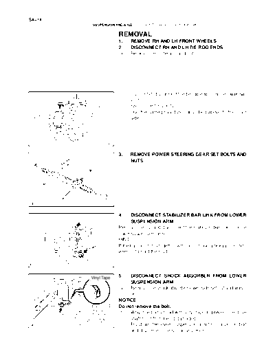
                       2.    DISCONNECT RH AND LH TIE ROD ENDS
                       (a)   Remove the cotter pin and nut.


                       (b)   Using SST, disconnect the tie rod end from the lower ball
                             joint.
                             SST 09610-20012
                       (c)   Use the same procedures described above to the other
 SST                         side.


              R13425


                       3.    REMOVE POWER STEERING GEAR SET BOLTS AND
                             NUTS


              F07278


                       4.     DISCONNECT STABILIZER BAR LINK FROM LOWER
                              SUSPENSION ARM
                       Remove the nut and disconnect the stabilizer bar link from the
                       lower suspension arm.
                       HINT:
                       If the ball joint turns together with the nut, use a hexagon (6 mm)
                       wrench to hold the stud.

              F07273


        Vinyl Tape     5.   DISCONNECT SHOCK ABSORBER FROM LOWER
                            SUSPENSION ARM
                       (a) Remove the shock absorber lower side set nut and wash-
                            er.
                       NOTICE:
                       Do not remove the bolt.
                       (b) Wrap the bolt's head with vinyl tape to prevent the drive
                            shaft boot from being damaged.
              F07274   (c) Pry down the lower suspension arm to remove the bolt
                            and disconnect the shock absorber.
                                                                                           SA-75
                    SUSPENSION AND AXLE    -   FRONT LOWER SUSPENSION ARM

                                   6.    DISCONNECT LOWER BALL JOINT FROM LOWER
                                         SUSPENSION ARM
                                   (a)   Remove the cotter pin and nut.


                                   (b)   Using SST, disconnect the lower ball joint from the lower
                                         suspension arm.
                                         SST 09628-62011


      SST

                          R12863


                                   7.  REMOVE LOWER SUSPENSION ARM
                                   (a) Place matchmarks on the front and rear cam plates and
                                       chassis frame.
             Matchmarks            (b) Remove the 2 cam plates, bolts, cams and lower suspen-
Matchmarks
                                       sion arm while slightly shifting the power steering gear
                                       rearward.
                                   NOTICE:
                                   Do not damage the power steering gear tubes.
                          R13282
◦ Jabse Service Manual Search 2026 ◦ Jabse Pravopis ◦ onTap.bg ◦ Other service manual resources online : Fixya ◦ eServiceinfo