Service Manuals, User Guides, Schematic Diagrams or docs for : . Car Manuals Toyota Tundra 2000-2006 Approved 04-06 techinfo.toyota.com ileaf 06toyrm 06toypdf 06rmsrc 06tundra sf1grfe fuepum ovi
<< Back | HomeMost service manuals and schematics are PDF files, so You will need Adobre Acrobat Reader to view : Acrobat Download Some of the files are DjVu format. Readers and resources available here : DjVu Resources
For the compressed files, most common are zip and rar. Please, extract files with Your favorite compression software ( WinZip, WinRAR ... ) before viewing. If a document has multiple parts, You should download all, before extracting.
Good luck. Repair on Your own risk. Make sure You know what You are doing.
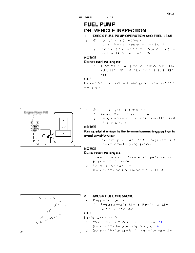
Image preview - the first page of the document
>> Download ovi documenatation <<
Text preview - extract from the document
                                                                                                SF-5
                                  SFI (1GR-FE)   -   FUEL PUMP


                                       FUEL PUMP                                                SF1Y6-01


                                       ON-VEHICLE INSPECTION
                                       1.    CHECK FUEL PUMP OPERATION AND FUEL LEAK
                                       (a)   When using the hand-held tester:
                                             (1) Connect the hand-held tester to the DLC3.
                                             (2) Turn the ignition switch to the ON position and the
                                                   hand-held tester main switch ON.
                                       NOTICE:
                                       Do not start the engine.
                                             (3) Enter the following menus: DIAGNOSIS / EN-
                                                   HANCED OBD II / ACTIVE TEST / FUEL PUMP /
                                                   SPD
                                       HINT:
                                       Please refer to the hand-held tester operator's manual for fur-
                                       ther details.


                                       (b)  When not using the hand-held tester:
Engine Room R/B
                                            (1) Remove the circuit opening relay.
                                            (2) Using a service wire, connect terminals FP and +B
                         +B
                                                 of the relay block.
                         FP            NOTICE:
                                       Pay careful attention to the terminal connecting position to
                                       avoid a malfunction.
                                            (3) Turn the ignition switch to the ON position, and
                              A23409             check that the fuel pump operates.
                                       NOTICE:
                                       Do not start the engine.
                                       (c) Check that there are no fuel leaks after performing main-
                                            tenance of the fuel system.
                                       (d) Turn the ignition switch off.
                                       (e) Disconnect the hand-held tester from the DLC3.


                                       2.    CHECK FUEL PRESSURE
   Fuel Tube Connector
                                       (a)   Prepare for inspection.
                                             (1) Prepare a new fuel tube, and take the fuel tube con-
                                                  nector out of the tube.
                                       HINT:
                                       Part No. 23801-31070
                                       (b) Prevent gasoline from spilling out (See page SF-1).
                                       (c) Disconnect the fuel pipe clamp (See page SF-1).
                              A23403   (d) Disconnect the fuel pipe No. 1 from the fuel main tube.
SF-6
                                          SFI (1GR-FE)   -   FUEL PUMP


                SST (Clip)                    (e)   Install SST (pressure gauge) as shown in the illustration
                              SST (Gauge)           by using SSTs and a fuel tube connector.
                                                    SST 09268-41047 (90467-13001, 95336-08070),
                                                             09268-45014 (09268-41200, 09268-41220,
                                                             09268-41250, 90467-13001)
              SST (T-joint)                   (f)   Wipe off any spattered gasoline.
                                              (g) Start the engine.
  Fuel Tube                                   (h) Measure the fuel pressure at idle.
                                                    Fuel pressure:
                       SST (Hose)                   281 to 287 kPa (2.87 to 2.93 kgfcm2, 40.8 to 41.7 psi)
                                              (i)   Stop the engine.
                                              (j)   Check that the fuel pressure remains as specified for 5
                                   SST
                                                    minutes after the engine has stopped.
                                                    Fuel pressure:
                                                    147 kPa (1.5 kgfcm2, 21 psi) or more
                                              If pressure is not as specified, check the fuel pump, pressure
SST (Hose)                                    regulator and/or injectors.
                                              (k) After checking the fuel pressure, disconnect the negative
                 Fuel Tube Connector
                                     A23417         (-) terminal cable from the battery carefully, and remove
                                                    the SST and fuel tube connector to prevent gasoline from
                                                    splashing.
                                              (l)   Reconnect the fuel tube to the fuel main tube.
                                              (m) Install the EFI fuel pipe clamp.
                                              (n) Check for fuel leak.
◦ Jabse Service Manual Search 2026 ◦ Jabse Pravopis ◦ onTap.bg ◦ Other service manual resources online : Fixya ◦ eServiceinfo