Service Manuals, User Guides, Schematic Diagrams or docs for : . Electronic Components Datasheets Active components Transistors LGE 3dd13001

<< Back | Home

Most service manuals and schematics are PDF files, so You will need Adobre Acrobat Reader to view : Acrobat Download Some of the files are DjVu format. Readers and resources available here : DjVu Resources
For the compressed files, most common are zip and rar. Please, extract files with Your favorite compression software ( WinZip, WinRAR ... ) before viewing. If a document has multiple parts, You should download all, before extracting.
Good luck. Repair on Your own risk. Make sure You know what You are doing.


Image preview - the first page of the document
3dd13001


>> Download 3dd13001 documenatation <<

Text preview - extract from the document
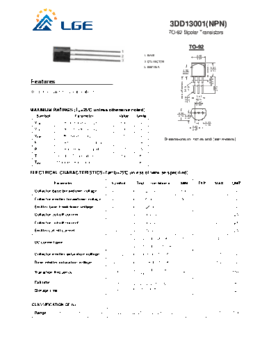
                                                                                      3DD13001(NPN)
                                                                                      TO-92 Bipolar Transistors

                                                                                                          TO-92
                                                                     1. BASE                                      4.45
                                                                                                                  5.21
                                                                     2. COLLECTOR


                                                                                                                            1.25MAX
                                                                     3. EMITTER                                                       4.32
                                                                                                2.92                                  5.33
                                                                                                MIN


Features


                                                                                                                                  MIN
                                                                                                                                  6.35 MIN
                                                                                            Seating Plane


                                                                                                                                       12.7
                                                                                               0.48
                                                                                               0.41
      power switching applications
                                                                                                                 3.43


                                                                                                        0.53
                                                                                                        0.41
                                                                                                                 MIN
                                                                                                                 2.41
                                                                                                                 2.67

MAXIMUM RATINGS (TA=25 unless otherwise noted)
                                                                                           3.18
  Symbol                 Parameter                Value        Units                       4.19 2.03
                                                                                                2.67
 VCBO         Collector -Base Voltage                 600        V                                                       1.14
                                                                                                                         1.40
                                                                                                               2.03
 VCEO         Collector-Emitter Voltage               400        V                                             2.67

 VEBO         Emitter-Base Voltage                      7        V
                                                                                    Dimensions in inches and (millimeters)
 IC           Collector Current -Continuous           0.2        A
 PC           Collector Power Dissipation             0.75      W
 TJ           Junction Temperature                    150       
 Tstg         Storage Temperature                -55-150        

ELECTRICAL CHARACTERISTICS (Tamb=25 unless otherwise specified)

             Parameter                        Symbol           Test      conditions         MIN                       TYP                MAX       UNIT

 Collector-base breakdown voltage             V(BR)CBO       IC= 100A , IE=0                 600                                                     V

 Collector-emitter breakdown voltage          V(BR)CEO       IC= 1mA , IB=0                  400                                                     V

 Emitter-base breakdown voltage               V(BR)EBO       IE= 100A, IC=0                     7                                                    V

 Collector cut-off current                      ICBO         VCB= 600V , IE=0                                                                100    A

 Collector cut-off current                      ICEO         VCE= 400V, IB=0                                                                 200    A

 Emitter cut-off current                        IEBO         VEB=     7V, IC=0                                                               100    A

                                               hFE(1)        VCE= 20V, IC= 20mA                10                                            40
 DC current gain
                                               hFE(2)        VCE= 10V, IC= 0.25 mA              5

 Collector-emitter saturation voltage         VCE(sat)       IC= 50mA, IB= 10 mA                                                             0.5     V

 Base-emitter saturation voltage              VBE(sat)       IC= 50 mA, IB= 10mA                                                             1.2     V

                                                             VCE= 20V, IC=20mA
 Transition frequency                            fT                                             8                                                   MHz
                                                             f = 1MHz

 Fall time                                       tf          VCC=45V, IC=50mA                                                                0.3     s

 Storage time                                    tS          IB1= -IB2=5mA                                                                   1.5     s


CLASSIFICATION OF hFE(1)

 Range       10-13       13-16      16-19     19-22          22-25        25-28        28-31                   31-34                  34-37        37-40
                          3DD13001(NPN)
                          TO-92 Bipolar Transistors


Typical Characteristics


◦ Jabse Service Manual Search 2024 ◦ Jabse PravopisonTap.bg ◦ Other service manual resources online : FixyaeServiceinfo