Service Manuals, User Guides, Schematic Diagrams or docs for : . Electronic Components Datasheets Various datasheets 74ls47
<< Back | HomeMost service manuals and schematics are PDF files, so You will need Adobre Acrobat Reader to view : Acrobat Download Some of the files are DjVu format. Readers and resources available here : DjVu Resources
For the compressed files, most common are zip and rar. Please, extract files with Your favorite compression software ( WinZip, WinRAR ... ) before viewing. If a document has multiple parts, You should download all, before extracting.
Good luck. Repair on Your own risk. Make sure You know what You are doing.
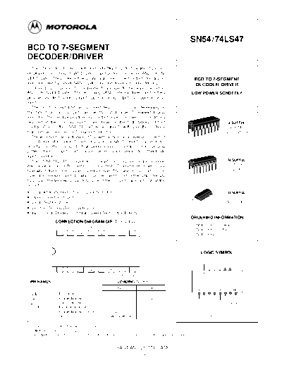
Image preview - the first page of the document

>> Download 74ls47 documenatation <<
Text preview - extract from the document
                                                                                                                   SN54/74LS47
BCD TO 7-SEGMENT
DECODER/DRIVER
   The SN54 / 74LS47 are Low Power Schottky BCD to 7-Segment Decod-
er / Drivers consisting of NAND gates, input buffers and seven AND-OR-IN-
VERT gates. They offer active LOW, high sink current outputs for driving                                               BCD TO 7-SEGMENT
indicators directly. Seven NAND gates and one driver are connected in pairs                                            DECODER/ DRIVER
to make BCD data and its complement available to the seven decoding
AND-OR-INVERT gates. The remaining NAND gate and three input buffers                                               LOW POWER SCHOTTKY
provide lamp test, blanking input / ripple-blanking output and ripple-blanking
input.
   The circuits accept 4-bit binary-coded-decimal (BCD) and, depending on
the state of the auxiliary inputs, decodes this data to drive a 7-segment display
indicator. The relative positive-logic output levels, as well as conditions
required at the auxiliary inputs, are shown in the truth tables. Output                                                                      J SUFFIX
configurations of the SN54 / 74LS47 are designed to withstand the relatively                                                                 CERAMIC
high voltages required for 7-segment indicators.                                                                                            CASE 620-09
   These outputs will withstand 15 V with a maximum reverse current of                                        16
                                                                                                                   1
250
◦ Jabse Service Manual Search 2024 ◦ Jabse Pravopis ◦ onTap.bg ◦ Other service manual resources online : Fixya ◦ eServiceinfo