Service Manuals, User Guides, Schematic Diagrams or docs for : . Electronic Components Datasheets Various datasheets 74ls795

<< Back | Home

Most service manuals and schematics are PDF files, so You will need Adobre Acrobat Reader to view : Acrobat Download Some of the files are DjVu format. Readers and resources available here : DjVu Resources
For the compressed files, most common are zip and rar. Please, extract files with Your favorite compression software ( WinZip, WinRAR ... ) before viewing. If a document has multiple parts, You should download all, before extracting.
Good luck. Repair on Your own risk. Make sure You know what You are doing.


Image preview - the first page of the document
74ls795


>> Download 74ls795 documenatation <<

Text preview - extract from the document
                                                                                                      SN54/74LS795
                                                                                                      SN54/74LS796
TRI-STATE OCTAL BUFFERS                                                                               SN54/74LS797
                                                                                                      SN54/74LS798
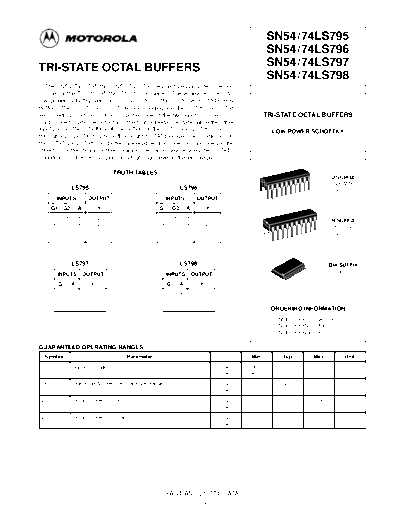
  The SN54 / 74LS795 thru SN54 / 74LS798 device types provide a second
source for the 71 / 81LS95 thru 71 / 81LS98 series. These devices are octal
low power Schottky versions of the 70/8095 thru 70/8098 3-STATE Hex
Buffers. The LS795 and LS797 are noninverting and the LS796 and LS798
are inverting functions. On each buffer, one of the two inputs is used as a                           TRI-STATE OCTAL BUFFERS
control line to gate the output into the high impedance state, while the other
input passes the data through the buffer. On the LS795 and LS796 access is                                    LOW POWER SCHOTTKY
through a 2-input NOR gate, with all eight 3-STATE enable lines common. On
the LS797 and LS798, four buffers are enabled from one common line and the
other four buffers from another common line. On all device types the 3-STATE
condition is achieved by applying a high logic level to the enable pins.

                                       TRUTH TABLES
                                                                                                                                   J SUFFIX
                                                                                                                                   CERAMIC
                     LS795                                              LS796                                                     CASE 732-03
                                                                                                20
           INPUTS             OUTPUT                          INPUTS             OUTPUT
                                                                                                      1
       G1       G2       A         Y                      G1       G2       A         Y
       H        X        X         Z                      H        X        X         Z
                                                                                                                                   N SUFFIX
       X        H        X         Z                      X        H        X         Z
                                                                                                                                   PLASTIC
       L        L        H         H                      L        L        H         L
                                                                                                                                  CASE 738-03
       L        L        L         L                      L        L        L         H          20
                                                                                                          1


                     LS797                                              LS798                                                      DW SUFFIX
           INPUTS            OUTPUT                           INPUTS            OUTPUT                                               SOIC
                                                                                                      20
                                                                                                                                  CASE 751D-03
            G        A         Y                               G        A         Y                             1

            H        X         Z                               H        X         Z
            L        H         H                               L        H         L
            L        L         L                               L        L         H                       ORDERING INFORMATION
                                                                                                              SN54LSXXXJ  Ceramic
                                                                                                              SN74LSXXXN Plastic
                                                                                                              SN74LSXXXDW SOIC

GUARANTEED OPERATING RANGES
  Symbol                                      Parameter                                        Min              Typ       Max           Unit
 VCC                 Supply Voltage                                                       54   4.5              5.0       5.5            V
                                                                                          74   4.75             5.0       5.25
 TA                  Operating Ambient Temperature Range                                  54   


◦ Jabse Service Manual Search 2024 ◦ Jabse PravopisonTap.bg ◦ Other service manual resources online : FixyaeServiceinfo