Service Manuals, User Guides, Schematic Diagrams or docs for : . Electronic Components Datasheets Various datasheets 74ls166
<< Back | HomeMost service manuals and schematics are PDF files, so You will need Adobre Acrobat Reader to view : Acrobat Download Some of the files are DjVu format. Readers and resources available here : DjVu Resources
For the compressed files, most common are zip and rar. Please, extract files with Your favorite compression software ( WinZip, WinRAR ... ) before viewing. If a document has multiple parts, You should download all, before extracting.
Good luck. Repair on Your own risk. Make sure You know what You are doing.
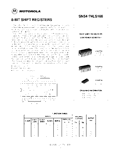
Image preview - the first page of the document

>> Download 74ls166 documenatation <<
Text preview - extract from the document
                                                                                                          SN54/74LS166
8-BIT SHIFT REGISTERS
   The SN54L/ 74LS166 is an 8-Bit Shift Register. Designed with all inputs
buffered, the drive requirements are lowered to one 54 / 74LS standard load.
By utilizing input clamping diodes, switching transients are minimized and
system design simplified.
   The LS166 is a parallel-in or serial-in, serial-out shift register and has a                               8-BIT SHIFT REGISTERS
complexity of 77 equivalent gates with gated clock inputs and an overriding
clear input. The shift/load input establishes the parallel-in or serial-in mode.                              LOW POWER SCHOTTKY
When high, this input enables the serial data input and couples the eight
flip-flops for serial shifting with each clock pulse. Synchronous loading occurs
on the next clock pulse when this is low and the parallel data inputs are
enabled. Serial data flow is inhibited during parallel loading. Clocking is done
on the low-to-high level edge of the clock pulse via a two input positive NOR
gate, which permits one input to be used as a clock enable or clock inhibit                                                       J SUFFIX
function. Clocking is inhibited when either of the clock inputs are held high,                                                    CERAMIC
holding either input low enables the other clock input. This will allow the                                                      CASE 620-09
system clock to be free running and the register stopped on command with                                 16
                                                                                                              1
the other clock input. A change from low-to-high on the clock inhibit input
should only be done when the clock input is high. A buffered direct clear input
overrides all other inputs, including the clock, and sets all flip-flops to zero.
◦ Jabse Service Manual Search 2024 ◦ Jabse Pravopis ◦ onTap.bg ◦ Other service manual resources online : Fixya ◦ eServiceinfo