Service Manuals, User Guides, Schematic Diagrams or docs for : . Electronic Components Datasheets Various datasheets 74ls221
<< Back | HomeMost service manuals and schematics are PDF files, so You will need Adobre Acrobat Reader to view : Acrobat Download Some of the files are DjVu format. Readers and resources available here : DjVu Resources
For the compressed files, most common are zip and rar. Please, extract files with Your favorite compression software ( WinZip, WinRAR ... ) before viewing. If a document has multiple parts, You should download all, before extracting.
Good luck. Repair on Your own risk. Make sure You know what You are doing.
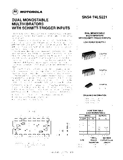
Image preview - the first page of the document

>> Download 74ls221 documenatation <<
Text preview - extract from the document
                                                                                            SN54/74LS221
DUAL MONOSTABLE
MULTIVIBRATORS
WITH SCHMITT-TRIGGER INPUTS
    Each multivibrator of the LS221 features a negative-transition-triggered                 DUAL MONOSTABLE
input and a positive-transition-triggered input either of which can be used as                MULTIVIBRATORS
an inhibit input.                                                                       WITH SCHMITT-TRIGGER INPUTS
    Pulse triggering occurs at a voltage level and is not related to the transition
time of the input pulse. Schmitt-trigger input circuitry for B input allows                     LOW POWER SCHOTTKY
jitter-free triggering for inputs as slow as 1 volt / second, providing the circuit
with excellent noise immunity. A high immunity to VCC noise is also provided
by internal latching circuitry.
    Once triggered, the outputs are independent of further transitions of the
inputs and are a function of the timing components. The output pulses can be                                            J SUFFIX
terminated by the overriding clear. Input pulse width may be of any duration                                            CERAMIC
relative to the output pulse width. Output pulse width may be varied from 35                                           CASE 620-09
                                                                                          16
nanoseconds to a maximum of 70 s by choosing appropriate timing                                     1
components. With Rext = 2.0 k and Cext = 0, a typical output pulse of 30
nanoseconds is achieved. Output rise and fall times are independent of pulse
length.
    Pulse width stability is achieved through internal compensation and is
                                                                                                                        N SUFFIX
virtually independent of VCC and temperature. In most applications, pulse                                               PLASTIC
stability will only be limited by the accuracy of external timing components.                                          CASE 648-08
                                                                                          16
    Jitter-free operation is maintained over the full temperature and VCC ranges
for greater than six decades of timing capacitance (10 pF to 10
◦ Jabse Service Manual Search 2024 ◦ Jabse Pravopis ◦ onTap.bg ◦ Other service manual resources online : Fixya ◦ eServiceinfo