Service Manuals, User Guides, Schematic Diagrams or docs for : . Electronic Components Datasheets Various datasheets 80m1
<< Back | HomeMost service manuals and schematics are PDF files, so You will need Adobre Acrobat Reader to view : Acrobat Download Some of the files are DjVu format. Readers and resources available here : DjVu Resources
For the compressed files, most common are zip and rar. Please, extract files with Your favorite compression software ( WinZip, WinRAR ... ) before viewing. If a document has multiple parts, You should download all, before extracting.
Good luck. Repair on Your own risk. Make sure You know what You are doing.
Image preview - the first page of the document

>> Download 80m1 documenatation <<
Text preview - extract from the document
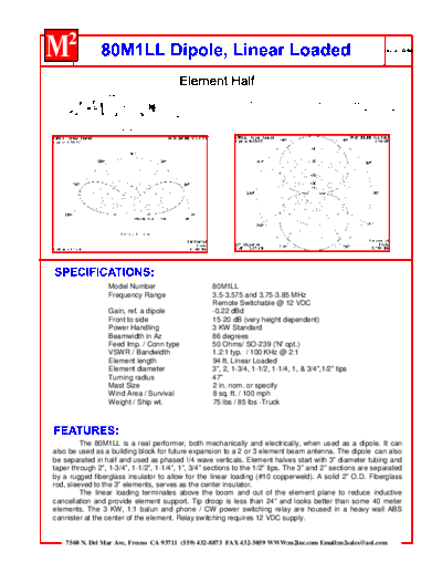
           1" DIA. FIBERGLASS ROD
                 2" DIA. FIBERGLASS
                 CENTER INSULATOR
                                      2x .058 x 48"        1-3/4x.058x60"   1-1/2x.058x60"   1-1/4x.058x60"   1x.058x60"   3/4x.049x48"   1/2 x .049 x 60"
                    3 x .125 x 180"
                                                                                                                                               57"

                                             FIBERGLASS
                                             SLEEVE INSULATOR

                         #10 AWG         1/2" DIA. SOLID
                         COPPERWELD      ALUM. POST


                      Model Number                                80M1LL
                      Frequency Range                             3.5-3.575 and 3.75-3.85 MHz
                                                                  Remote Switchable @ 12 VDC
                      Gain, ref. a dipole                         -0.22 dBd
                      Front to side                               15-20 dB (very height dependent)
                      Power Handling                              3 KW Standard
                      Beamwidth in Az                             86 degrees
                      Feed Imp. / Conn type                       50 Ohms/ SO-239 ('N' opt.)
                      VSWR / Bandwidth                            1.2:1 typ. / 100 KHz @ 2:1
                      Element length                              94 ft. Linear Loaded
                      Element diameter                            3", 2, 1-3/4, 1-1/2, 1-1/4, 1, & 3/4",1/2" tips
                      Turning radius                              47"
                      Mast Size                                   2 in. nom. or specify
                      Wind Area / Survival                        8 sq. ft. / 100 mph
                      Weight / Ship wt.                           75 lbs / 85 lbs -Truck


         The 80M1LL is a real performer, both mechanically and electrically, when used as a dipole. It can
also be used as a building block for future expansion to a 2 or 3 element beam antenna. The dipole can also
be separated in half and used as phased !/4 wave verticals. Element halves start with 3" diameter tubing and
taper through 2", 1-3/4", 1-1/2", 1-1/4", 1", 3/4" sections to the 1/2" tips. The 3" and 2" sections are separated
by a rugged fiberglass insulator to allow for the linear loading (#10 copperweld). A solid 2" O.D. Fiberglass
rod, sleeved to the 3" elements, serves as the center insulator.
         The linear loading terminates above the boom and out of the element plane to reduce inductive
cancellation and provide element support. Tip droop is less than 24" and looks better than some 40 meter
elements. The 3 KW, 1:1 balun and phone / CW power switching relay are housed in a heavy wall ABS
cannister at the center of the element. Relay switching requires 12 VDC supply.


    7560 N. Del Mar Ave, Fresno CA 93711 (559) 432-8873 FAX 432-3059 WWW:m2inc.com Email:[email protected]
◦ Jabse Service Manual Search 2024 ◦ Jabse Pravopis ◦ onTap.bg ◦ Other service manual resources online : Fixya ◦ eServiceinfo