Service Manuals, User Guides, Schematic Diagrams or docs for : . Rare and Ancient Equipment CAMBRIDGE Audio Azur 640C hfe_cambridge_audio_azur_640c_service
<< Back | HomeMost service manuals and schematics are PDF files, so You will need Adobre Acrobat Reader to view : Acrobat Download Some of the files are DjVu format. Readers and resources available here : DjVu Resources
For the compressed files, most common are zip and rar. Please, extract files with Your favorite compression software ( WinZip, WinRAR ... ) before viewing. If a document has multiple parts, You should download all, before extracting.
Good luck. Repair on Your own risk. Make sure You know what You are doing.
Image preview - the first page of the document
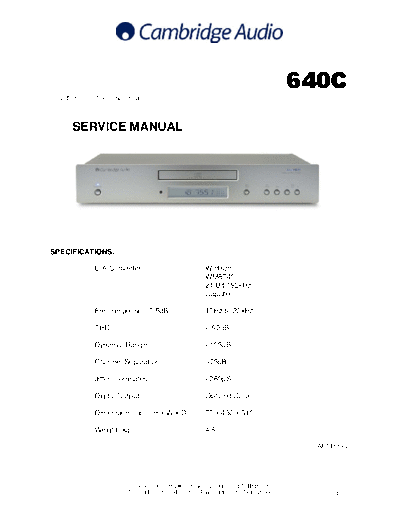
>> Download hfe_cambridge_audio_azur_640c_service documenatation <<
Text preview - extract from the document
                                                                             640C
Issue Date: 22nd December 2004
________________________________________________________________________

       SERVICE MANUAL


________________________________________________________________________

SPECIFICATIONS:

              D/A Converter                        Wolfson
                                                   WM8740
                                                   24-Bit/192kHz
                                                   Capable

              Freq response (-0.5dB)               10Hz to 20kHz

              THD                                  <-92dB

              Dynamic Range                        <105dB

              Channel Separation                   >75dB

              Jitter (correlated)                  <260pS

              Digital Outputs                      Opt and Coax

              Dimension (mm) (H x W x D)           70 x 430 x 310

              Weight (kg)                          4.6

                                                                               AP14839/2


                         Gallery Court Hankey Place London SE1 4BB UK
                         Tel: +44 (0)20 7940 2200 Fax: +44 (0)20 7940 2233          1
             640C SERVICE MANUAL
                   TABLE OF CONTENTS

Safety Precautions & Important Notes   3

Laser Safety Precautions               4

Exploded Assembly Diagram              5

Main Assembly BOM (Silver Unit)        6-8

Front Panel PCB Schematic              9

Front Panel PCB Layout (Top Side)      10

Front Panel PCB Layout (Bottom Side)   11

Front Panel PCB BOM (Silver Unit)      12/13

Servo PCB Schematic                    14

Servo PCB Schematic (Power Supply)     15

Servo PCB Layout (Top Side)            16

Servo PCB Layout (Bottom Side)         17

Servo PCB BOM                          18/19

DAC PCB Schematic                      20

DAC PCB Layout (Top Side)              21

DAC PCB Layout (Bottom Side)           22

DAC PCB BOM                            23

Mains Input PCB Schematic              24

Mains Input PCB Layout (Top Side)      25

Mains Input PCB Layout (Bottom Side)   26

Mains Input PCB BOM                    27

IC Pin Layout Details                  28-33

Silver / Black Differences BOM         34


                                               2
  SAFETY PRECAUTIONS & IMPORTANT NOTES

        1.Check that the rear of the product indicates the correct supply voltage
        for you area.

                         2. The lighting flash with the arrowhead within an equilateral
                         triangle is intended to alert the user or service agent to the
                         presence of dangerous voltages within the product enclosure
                         that may be of sufficient magnitude to constitute a risk of
                         electric shock to persons.

                         3. The exclamation point within an equilateral triangle is
                         intended to alert the user or service agent to the presence of
                         important operating and maintenance (Servicing) instructions
                         in the literature accompanying the appliance.

        4. This product complies with EEC Low Voltage (73/23/EEC) and
        Electromagnetic Compatibility (89/336/EEC) Directives when used and
        serviced in accordance with this manual. For continued compliance all
        components marked safety and EMC critical must only be replaced by
        Cambridge Audio approved parts.

        5. Any unauthorised design alterations or additions will void the
        manufacturer's warranty; furthermore the manufacturer cannot accept
        responsibility for personal injury or property damage resulting therefrom.

        6. When servicing, care should be taken to observe the original routing
        and dressing of the leads and it should be confirmed that they have been
        returned to normal after re-assembly.

        Notes on chip component replacement
        Never reuse a component that has been removed from a PCB
        Notice that the minus side of a tantalum capacitor may be damaged by heat


COPYRIGHT NOTICE.
◦ Jabse Service Manual Search 2026 ◦ Jabse Pravopis ◦ onTap.bg ◦ Other service manual resources online : Fixya ◦ eServiceinfo