Service Manuals, User Guides, Schematic Diagrams or docs for : . Rare and Ancient Equipment CAMBRIDGE Audio 540P hfe_cambridge_audio_540p_640p_service
<< Back | HomeMost service manuals and schematics are PDF files, so You will need Adobre Acrobat Reader to view : Acrobat Download Some of the files are DjVu format. Readers and resources available here : DjVu Resources
For the compressed files, most common are zip and rar. Please, extract files with Your favorite compression software ( WinZip, WinRAR ... ) before viewing. If a document has multiple parts, You should download all, before extracting.
Good luck. Repair on Your own risk. Make sure You know what You are doing.
Image preview - the first page of the document
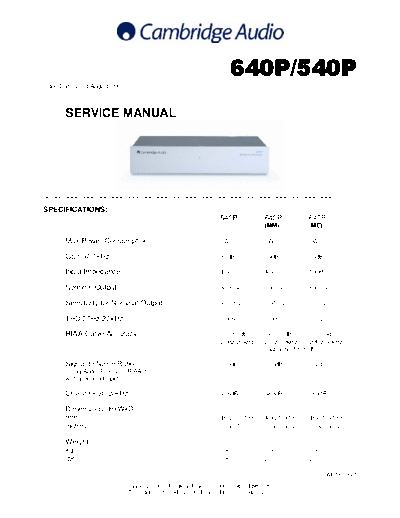
>> Download hfe_cambridge_audio_540p_640p_service documenatation <<
Text preview - extract from the document
                                                                    640P/540P
Issue Date: 23rd August 2005
________________________________________________________________________

       SERVICE MANUAL


________________________________________________________________________

SPECIFICATIONS:
                                                              540P           640P           640P
                                                                             (MM)           (MC)

       Max Power Consumption                                  5W             5W             5W

       Gain @ 1kHz                                            39dB           39dB           55dB

       Input Impedance                                        47k            47k            100R

       Nominal Output                                         300mV          300mV          300mV

       Sensitivity for Nominal Output                         3.35mV         3.35mV         0.5mV

       THD 20Hz-20kHz                                         0.009%         0.005%         0.002%

       RIAA Curve Accuracy                                    +/-0.65dB      <+/-0.3dB         <+/-0.3dB
                                                              25Hz-20kHz     20hz-50kHz        20Hz-50kHz
                                                                             (Subsonic filter off)

       Signal to Noise Ratio                                  >85db          >86dB          >72dB
       Using Audio Precision RIAA-1
       with grounded inputs.

       Crosstalk @ 20kHz                                      >76dB          >83dB          >69dB

       Dimensions (HxWxD)
       mm                                                     46x215x133     46x215x133     46x215x133
       inches                                                 1.8x8.5x5.2    1.8x8.5x5.2    1.8x8.5x5.2

       Weight
       kg                                                     0.8            0.9            0.9
       lbs                                                    1.8            2              2

                                                                                                   AP18705/1
                               Gallery Court Hankey Place London SE1 4BB UK
                               Tel: +44 (0)20 7940 2200 Fax: +44 (0)20 7940 2233                      1
              540P & 640P SERVICE MANUAL

                          TABLE OF CONTENTS


Safety Precautions & Important Notes          3

540P/640P Main Assembly BOM                   4

540P Main PCB Schematic                       5

540P Main PCB Layout (Top Side)               6

540P Main PCB Layout (Bottom Side)            7

540P Main PCB BOM                             8-9

640P Main PCB Schematic                       10

640P Main PCB Layout (Top Side)               11

640P Main PCB Layout (Bottom Side)            12

640P Main PCB BOM                             13-15

IC Pin Layout Details                         16


                                                      2
  SAFETY PRECAUTIONS & IMPORTANT NOTES

        1.Check that the rear of the product indicates the correct supply voltage
        for you area.

                         2. The lighting flash with the arrowhead within an equilateral
                         triangle is intended to alert the user or service agent to the
                         presence of dangerous voltages within the product enclosure
                         that may be of sufficient magnitude to constitute a risk of
                         electric shock to persons.

                         3. The exclamation point within an equilateral triangle is
                         intended to alert the user or service agent to the presence of
                         important operating and maintenance (Servicing) instructions
                         in the literature accompanying the appliance.

        4. This product complies with EEC Low Voltage (73/23/EEC) and
        Electromagnetic Compatibility (89/336/EEC) Directives when used and
        serviced in accordance with this manual. For continued compliance all
        components marked safety and EMC critical must only be replaced by
        Cambridge Audio approved parts.

        5. Any unauthorised design alterations or additions will void the
        manufacturer's warranty; furthermore the manufacturer cannot accept
        responsibility for personal injury or property damage resulting therefrom.

        6. When servicing, care should be taken to observe the original routing
        and dressing of the leads and it should be confirmed that they have been
        returned to normal after re-assembly.

        Notes on chip component replacement
        Never reuse a component that has been removed from a PCB
        Notice that the minus side of a tantalum capacitor may be damaged by heat


COPYRIGHT NOTICE.
◦ Jabse Service Manual Search 2026 ◦ Jabse Pravopis ◦ onTap.bg ◦ Other service manual resources online : Fixya ◦ eServiceinfo