Service Manuals, User Guides, Schematic Diagrams or docs for : . Rare and Ancient Equipment AVID Diva ve_avid_diva

<< Back | Home

Most service manuals and schematics are PDF files, so You will need Adobre Acrobat Reader to view : Acrobat Download Some of the files are DjVu format. Readers and resources available here : DjVu Resources
For the compressed files, most common are zip and rar. Please, extract files with Your favorite compression software ( WinZip, WinRAR ... ) before viewing. If a document has multiple parts, You should download all, before extracting.
Good luck. Repair on Your own risk. Make sure You know what You are doing.


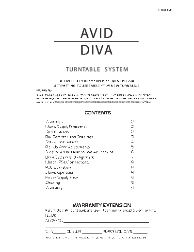
Image preview - the first page of the document
ve_avid_diva


>> Download ve_avid_diva documenatation <<

Text preview - extract from the document
                                                                                                                                   ENGLISH


                                                            AVID
                                                            DIVA
                                               TUR NTAB L E S Y S TE M
                                       PLEASE FULLY READ THIS DOCUMENT BEFORE
                                    ATTEMPTING TO ASSEMBLE YOUR NEW TURNTABLE
                   PACKAGING
                   Save all the packing in a dry place away from fire hazard. The DIVA Turntable is a precision instrument
                   and the packaging has been especially designed so that all component parts are safe during transportation.
                   We recommend that you do not transport with turntable assembled and never with the bearing fitted.


                                                                CONTENTS
                            Warnings                                                                        2
                            Mains Supply Frequency                                                          2
                            Specifications                                                                  2
                            Box Contents and Drawings                                                       3
                            Set-Up Instructions                                                             4
                            Pick-Up Arm Adjustments                                                         5
                            Suspension Installation and Adjustment                                          6
                            Drive System and Alignment                                                      7
                            Motor/PSU Connections                                                           8
                            PSU Operation                                                                   8
                            Clamp Operation                                                                 8
                            Power Supply Fuse                                                               9
                            Cleaning                                                                        9
                            Warranty                                                                        9
----------------------------------------------------------------------------------------------------------------------------------------------


                                                     WARRANTY EXTENSION
                            Return slip with your details and you will sent our extended 5 year warrenty.
                            NAME:____________________________________________
                            ADDRESS:_________________________________________
                            __________________________________________________
                            S/N______ DEALER:__________PURCHASE DATE_______
                            Return to: AVID. Unit 52, 137 NorthGate, Alconbury Airfield, Huntingdon, Cambs. PE28 4WX ENGLAND
WARNINGS                                                                      SPECIFICATIONS

Keep the Drive Belt, Pulley and Platter                                       DRIVE                       : Belt Drive
free from contamination.
                                                                              SPEEDS                      : 33 and 45 RPM
If the Drive Belt is dirty, replacement is
                                                                              PLATTER MASS                : 3.3Kg
required. It is not possible to clean.
Symptoms that the belt needs changing;                                        BEARING                     : Inverted Stainless Steel, Tungsten/Sapphire Thrust
Speed instability and loss of dynamics.
                                                                              SUSPENSION                  : 3 Point Variable Frequency Springs

Do not expose unit to rain or water.                                          FREQUENCY                   : 4.5 Hz (Variable)


The Power Supply contains voltages that                                       PICK-UP ARM                 : SME & REGA RB300 Arm Boards standard.
                                                                              OPTIONS                       Adapters for REGA RB1000, Wilson Benesch,
can cause serious injury or death. There                                                                    Dynavector, Triplanar & Graham available.
                                                                                                            Different arm mountings to order.
are no user serviceable parts and no
reason to open. In situations of failure                                      PICK-UP ARM                 : 9" Pick-Up Arms onto Standard arm/tube rods.
return to approved dealer or agent.                                           VARIANTS                     12" Pick-Up Arms onto Long arm/tube rods.
                                                                                                           (When fitting 12" Arms it is recommended that
                                                                                                            the Long Suspension Bars are used.)
Do not use or let liquid cleaners enter the
Power Supply.                                                                 MOTOR                      : 24v AC Synchronous 50/60Hz

                                                                              MAINS SUPPLY                : Voltage and Frequency Specified on PSU rear.
The Platter surface may be cleaned with
normal glass cleaner.                                                         CONSUMPTION                 : 5 watts Max.


                                                                              DIMENSIONS                  : Turntable                 460 x 375 x 130mm
The Main Bearing contains a Sapphire Cup                                      (W x H x D)                 : PSU                       160 x 60 x 138mm
Jewel and this can be damaged if proper
care is not taken. This will effect or stop                                   WEIGHT                      : 11.2Kg (Shipping 13.0Kg)
the turntable working correctly.
                                                                              Improvements may result in specification or feature changes without notice.
                                                                              Illustrations may differ slightly for production models.
             MAINS SUPPLY FREQUENCY
Local electrical supply frequency is either 50Hz or 60Hz.
Regions with dual frequencies will be supplied with both
                                                                                                                      m)
drive pulleys so that the correct speed can be achieved.                                                          5m
                                                                                                               (65
                                                                                                           m
                                                                                                       0m
To change the drive pulley, remove screw with wrench                                               50
supplied and pull off pulley. Replace with correct pulley
and correctly align. Finally replace screw.
                                                                                                                                                                       375mm (465mm)


               Pulley         DRIVE PULLEY ALIGNMENT
     Screw                 Use inside of drive pulley for correct alignment


     Spindle
                                                   Spindle top level with
                                                   inside of drive pulley
                                                1.72mm Gap

               Motor


! IF IN DOUBT CONTACT YOUR DEALER
                                                                                                                     460mm (600mm)


                                                                              ( ) Bracketed figures show maximum dimensions when using 2 x 12" arms and long Suspension Bars.


                                                                                                                                                                                  2
Box Contents and Drawings


                                                       Weight 1              Arm Board 1               Tools 5


                Platter 1                       Suspension Bars 3                 Arm Rods & Tube 2/1


                                                                                            Drive Pulley
                                                                                          Another pulleys will be
                                                                                          included if specified or
                                                                                          needed in your region
             Suspension Housings 3                                      Motor 1


   Clamp 1             Drive Belt 1                Main Bearing / Hub 1                   Subchassis 1


      Bearing Ball 1                      Power Cord 1
                                      Some regions will be supplied
                                      by the local importer or dealer
                                                                                  Power Supply 1

                                                                                                                     3
SET - UP INSTRUCTIONS
    The Diva should be installed on a firm level surface for the best results.
    Steps 1-8 show pick-up arm installation and subchassis assembly.
    Steps 9-12 show pick-up arm alignment.
    Steps 13-16 show suspension installation and alignment.
    Steps 17-20 show motor and8  drive belt installation.


1   Fit the 3 Suspension Bars to the Subchassis.
    Using the 4mm wrench supplied, fit the M5 bolts,
    securely fixing the bars.

2   Fit the chosen pick-up arm to the correct arm board.
    Feed the arm cable through the large hole in the side.
    Pass the arm leads through the "Arm Tube" and insert
    tube into arm board, not locking in place.
    Push arm lead through hole in subchassis and leave loose.

3   Insert Arm Rods into subchassis, not locking in place.

4   Slide arm board onto rods, pushing arm tube into
    subchassis and arm board at same time.

5   Secure arm lead to subchassis using the 2.5mm wrench.
    This may need readjusting after stage 6.


6   Align the arm board to the grooves at the end of arm rods,
    for correct arm geometry. Lock all arm board and subchassis                                                    Pick-up Arm
    screws with the wrenches provided.
7   Readjust arm leads as required.                                                                          Pick-up Arm Leads

8   When fitting 2 arms repeat steps 1-7 opposite.
    If only using one arm, fit the balance weight to                                         2
    the subchassis and lock into position.
                                                                                    6

                                                                         Arm Tube                         Pick-up Arm
                                                                                                          Board

                                                                  4

                               Balance Weight   Spindle                                           INSET
                                                with cover
                      8
                                                                                        Arm Rod

                                                                                3
                                                 Subchassis
                                                                                                    6      Pick-up Arm Board


             Suspension Bars
                                                                                                                Arm Rod
                                                              Arm Lead
                                            1                 Clamp
                                                                                                                                   Alignment
                                                                5                                          Arm Board lock screws
                                                                                                           Use 1.5mm wrench
                                                                                                                                   Groove


                                                                                                                                               4
     PICK-UP ARM ADJUSTMENTS


9    Clean the spindle of any sticky residue from the spindle cover
     making sure the top of spindle is spotless.
     Place the Tungsten Bearing Ball into the top of the spindle.
     DO NOT USE ANY GLUES OR LUBRICANTS.
     THIS BEARING IS DESIGNED TO RUN DRY.

                                                                            Clamp
10   Fit Hub/Bearing to spindle.
     The bearing thrust is a sapphire jewel and extreme care
     should always be taken against sudden impacts.
                                                                                     12

11   Carefully fit the Platter to the Hub without
     dropping onto the bearing. The location
     ring will help with alignment.
12   Place record onto platter and clamp.

                                                                                    Record

     It is now recommended to make the set-up
     adjustments to the pick-up arm before the
     suspension is fitted.


                                                                                     Platter


                                                                                                 11
     Before moving to the next section,
     removing the clamp, record and
     platter is recommended.

                                                                                           Hub

                                                                                          10

                                                    Tungsten Bearing Ball
                                                                               9


                                                      Bearing Spindle


                                                                                                      5
     SUSPENSION INSTALLATION AND ADJUSTMENT

13   Remove M5 retaining bolt from the suspension cover with wrench provided.
     Insert end of spring into suspension bar as diagram. Fit all 3 units.
14   The Platter should now be leveled by adjusting each spring in turn.
     This is done by holding spring and turning foot as in diagram below.
     Move the feet so that the springs do not touch the adjusters lower body.
15   The base of the suspension bars should be about 3 - 5mm from the top of foot.
     Once the motor and drive belt have been fitted readjustment may be required.

16   The suspension will be correctly set when the drive hub is level with the
     drive pulley and the platter, subchassis and pick-up arm move in a smooth
     pistonic motion without any wobble.
     Once correctly set the suspension covers can be refitted so that
     the suspension bars do not touch.


                                          13

                                                                       14


                                                                                     6
      DRIVE SYSTEM AND ALIGNMENT


17    With the platter removed place the motor in close proximity to the drive hub
      within the cut-out in the subchassis. Pass the motor lead under the subchassis.

18    The Drive Belt should only be handled with clean hands. If it becomes dirty the
      turntable will not perform correctly and will need replacing.
      Drive Belts cannot be cleaned so handle with great care.

      Fit the Drive Belt by removing the platter. Place belt around hub
      and then around drive pulley. Refit platter, record and
      clamp and recheck for alignment.


19    Correct alignment of the suspension
      will ensure the platter is level and the
      hub in line with drive pulley.

20    Finally connect PSU to the motor and
      start. Recheck suspension is smooth
      and fit suspension covers.
      More important than absolute level is
      the smooth operation of the suspension,
      therefore bubble levels are not required.                   Drive Belt


                                                                  18


                                                                                                                 20


                                                                                                  Drive Pulley
                                                                               17

                                                                                    AV I D

                                                                                             Drive Motor
     19

                               Platter

          33 RPM                                     Drive Belt
          45 RPM

                                                     Drive Hub

      Drive
      Motor                                       Subchassis


                   3 - 4mm


                                                                                                                      7
MOTOR / PSU CONNECTIONS                                                             PSU OPERATION

                                                                                                              Play indicator
                                              IEC Mains Inlet
                      PSU (Rear)


    Motor

                                                                         Fuse                  Start / Stop switch
                                                                         Holder
                            Motor Lead
                            Connector
                                                                     2            Operation of the turntable is done by the rotary switch
                                                                                  on the front panel.
                                                                                  When turned clockwise to switch on a red light shines
                                               Supplied Mains Cord


                                                                                  to confirm power.
                                                                                  Turn anti-clockwise to switch off.
                                                                                  This also disconnects the mains supply.
            1
                                                                                  Speed change is done by moving the drive belt from
                                                                                  one pulley diameter to another.


                                         Mains Supply
                                                                                    CLAMP OPERATION

1 Motor connection to PSU
  The locking connector at the end of the motor                                   The clamp supplied is an
  lead will only fit one way and should then be                                   integral part of the Diva
  locked into position.                                                           design and should be
2 Use IEC type mains lead supplied.                                               used when a record
                                                                                  is played.

!   DURING OPERATION THE MOTOR WILL BECOME HOT.
    THIS IS NORMAL AND DOES NOT EFFECT PERFORMANCE.                               After placing the record onto the platter screw
                                                                                  the clamp onto the spindle thread clockwise.
    FOR BEST PERFORMANCE WE RECOMMENDED THE POWER SUPPLY                          Take care not to hit or cross-thread the spindle.
    IS PLACED AWAY FROM THE TURNTABLE AND SUPPORT SURFACE.                        Screw anti-clockwise to remove the clamp.


                                                                                                                                       8
POWER SUPPLY FUSE                                                      WARRANTY
The mains socket is an IEC type and you should use the supplied        2 YEAR LIMITED WARRANTY - TERMS AND CONDITIONS.
lead or a suitable alternative fused at 3 Amps where fitted.
The socket contains an input fuse and in case of failure this should   AVID warrants this product designated herein to be free of
be checked first. Fuse ratings are;                                    manufacturing defects in material and workmanship,
                                                                       subject to the conditions hereinafter set forth, for a period
100-120v = 250v 2 Amp              220-240v = 250v 1 Amp
                                                                       of twenty-four (24) months from the date of purchase by the
                                                                       original purchaser or no later than thirty (30) months
CHANGING FUSE.                                                         from the date of shipment to an authorized AVID agent,
Always exchange for the correct value.                                 whichever come first, except for the following items;
                                                                       1. Sapphire Thrust Bearing
1. Use of flat screwdriver to open                                     2. Drive Belt
   the fuse holder from socket.                                        These items have no warranty, however replacements may
2. Remove fuse and check.                                              be issued by AVID at our discretion.
   If faulty replace with new one.
   This will click into place.                                         This warranty is subject to the following conditions and
3. Push fuse holder back into the                                      limitations. The warranty is void and inapplicable if the
   socket until flush.                                                 product has been used or handled other than in accordance
                                                                       with the instructions in this manual, abused or misused,

!   CONTACT YOUR SUPPLIER IF IN DOUBT
                                                                       damaged by accident or neglect or in being transported, or
                                                                       if the defect is due to the product being repaired or tampered
                                                                       with by anyone other than AVID or an agent with prior
                                                                       authorization. The product must be packed and returned, in
                                                                       its original packing, to AVID or an authorized agent by the
                                                                       customer at their expense. (If no packing is available, AVID
                                                                       will supply this as a chargeable item.) AVID will pay the
                                                                       return freight of its choice. Any claim arising should be made
                                                                       in the first instance in writing to AVID or authorized agent
CLEANING                                                               direct before returning any product. If product needs to be
                                                                       returned a written description of the defect and a photocopy
                                                                       of the original purchase receipt must accompany it. This
                                                                       receipt must clearly list the model and serial number, date
To maintain the visual appearance of the DIVA, occasionally dust       of purchase, the name and address of the purchaser and
the surfaces with a normal duster. Do not use benzene, thinner or      authorized dealer and the price paid by the purchaser.
chemical solvent or wipe with a chemically treated cloth.              AVID reserves the right to modify the design of any product
                                                                       without obligation to purchasers of previously manufactured
Fingerprints, greasy marks or similar smudges on the metal work        products and to change the prices or specifications of any
can be removed with a dry cloth, mild soapy water or alcohol           product without notice or obligation to any person.
cleaner. Never use an abrasive cleaner.                                Any implied warranties relating to the above product shall be
                                                                       limited to the duration of this warranty. This warranty does
Do not attempt to clean the drive belt with anything. If dirty or      not extend to any incidental or consequential costs or
greasy it will probably need replacing.                                damages to the purchaser.
                                                                       WARRANTOR.
The glass top of the platter can be cleaned with glass cleaner.        Inquiries regarding the above Limited Warranty may be sent
                                                                       to the address below.

                                                                       AVID. Unit 52, 137 North Gate, Alconbury Airfield, Alconbury,
                                                                       Huntingdon, Cambridgeshire PE28 4WX England


                                                                       EC Declaration of Conformity
                                                                       We declare that our DIVA PSU used in our DIVA turntables conform to the following directives
                                                                       and harmonized international standards.
                                                                       LVD (73/23/EEC) Low voltage directive. EMC (89/36/EEC) Electromagnetic conformity.
                                                                       CENELEC HD21/22 Flexible cables and cords. BS EN 60065: 1994 Safety requirements for
                                                                       mains operated electronic and related apparatus for household and similar general use.
                                                                       EN 55013: 1990 Electromagnetic Emissions. EN 55020: 1988 Electromagnetic Immunity.

                                                                       C.Mas
                                                                       Proprietor
                                                                       AVID


                                                                                                                                                                9


◦ Jabse Service Manual Search 2026 ◦ Jabse PravopisonTap.bg ◦ Other service manual resources online : FixyaeServiceinfo