Service Manuals, User Guides, Schematic Diagrams or docs for : . Rare and Ancient Equipment B&K 1471 Instruction Manual

<< Back | Home

Most service manuals and schematics are PDF files, so You will need Adobre Acrobat Reader to view : Acrobat Download Some of the files are DjVu format. Readers and resources available here : DjVu Resources
For the compressed files, most common are zip and rar. Please, extract files with Your favorite compression software ( WinZip, WinRAR ... ) before viewing. If a document has multiple parts, You should download all, before extracting.
Good luck. Repair on Your own risk. Make sure You know what You are doing.


Image preview - the first page of the document
1471 Instruction Manual


>> Download 1471 Instruction Manual documenatation <<

Text preview - extract from the document
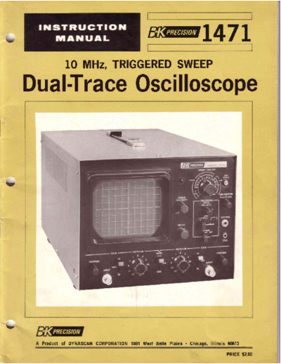
                                                               !471
               10 MHz,TRIGGERED
                             SWEEP
    Dual-T aceOscIIosco
          r     I     p


v


        \


v

     A Productof DYNASCAN         1801West Belle Plaine. Chicago,
                        CORP0RATI0N                             lllinois 60613

                                                                        PRTCE
                                                                            $2.00
l v


       INSTRUCTION
                MANUAL
                             FOR

          B & K.PRECISION
           MODELL47T
 b          TRIGGERED
      10 MHz,       SWEEP
      DUAL.TRACE
              OSCILLOSCOPE


        DIVISION DYNASCAN
                OF      CORPORATION
             | 801 W. Belle PloineAvenue
               C h i c o g o ,l l l i n o i s 6 0 6 I 3


  v
                                 TABLE OF CONTENTS               \t
                                                         Page
INTRODUCTION

FEATURES

SPECIFICATIONS

OPERATOR'S CONTROLS, INDICATORS AND FACILITIES

OPERATING INSTRUCTIONS
  Initial Starting Procedure                                9
  Single-Trace  WaveformObservation                         9
  CalibratedVoltage Measurement                            10
  CalibratedTime Measurement                               ll
  External Horizontal Input (X-Y Operation) . . .          l2
  Z-Axis lnput                                             t2
  Dual-Trace  WaveformObservation                          t2

DUAL-TRACE APPLICATIONS
  Introduction . .                                          14
  F re q u e n c y D i v i d e rWa v e fo rms
                                           ...              14
  Dvide-by-8CircuitWaveforms...                             14
  Digital Circuit Time Relationships                        14
  Gated Ringing Circuit                                     14
  DelayUneTests                                      ......16    v
  StereoAmplifier Servicing                                l6
  TelevisionServicing                                      t7

SINGLE-TRACE APPLICATIONS
   Introduction . .                                        18
   TelevisionServicing                                     18
   SignalTracing and Peak-to-Peak Voltage Readings         t9
   CompositeVideo WaveformAnalysis                         t9
   Sync PulseAnalysis                                      r9
  VITS (Vertical Interval Test Signal) . . .               2l
   Vectorscope Operation                                   23

TELEVISION ALIGNMENT
  Introduction . .                                         26
   Importance Sweep
            of    Alignment                                26
   SweepAlignment Methods                                  27
   Tuner Alignment                                         28
   IF Alignment                                            29
   ChromaAlignment...                                      29


                                                                 v
v                               TABLE OF CONTENTS

                                                        Page
    FM RECEIVER ALIGNMENT                           , . . . 3 1

    PHASEMEASUREMENT                                      3l

    FREQUENCY
            MEASUREMENT

    SQUARE WAVE TESTING OF AMPLIFIERS
      Introduction .                                      33
      TestingProcedure                                    34
                                                          34

    CIRCUITDESCRIPTION
      General                                            38
       Vertical Preamplifiers                            38
       Mode Iogc                                         38
       Vertical Amplifier                                38
       Trigger
             Circuit                                     38
       SyncAmplifierandInverter                          38
                                                         40
                                                         40
                                                         40
                                                         40
b                                                        40
                                                         50

    CALIBRATION ADJUSTMENTS
      CH I and CH2 DC Balance . . .                      40
      l12 and l/5 Attenuator Balance                     40
      Vertical Gain Adjustment                           40
      Horizontal Position Adjustment . . .               40

    WARRANTYINSTRUCTIONS                                 42

    WARRANTY                                             43


v
                                                        INTRODUCTION
   The B & K-Precision Model l47I Dual-Trace Oscil-                       The dual-tracefeature,togetherwith the 10 MHz band-
loscopeis a laboratory-quality,
observingand measuring
                               professional instrument for
                          waveformsin electronic circuits.
                                                                       width, wide range of sweep speeds,and high sensitivity
                                                                       provided,-make this the ideal oscilloscope a broadrange
                                                                                                                for
                                                                                                                                    v
Dual vertical inputs are provided for simultaneous viewing             of applications,including troubleshootingand repairing
of two waveforms. Low-frequency, low repetition rate                   electionic equipment, research and development,and
waveformsare chopped at a 200 kHz rate to provide for                  laboratorvinstruction.
simultaneous  viewing. Alternate sweepof the two inputs
permitssimultaneous  viewingof high-speed, high repetition-
rate waveforms.


                                                            FEATURES
DUAL TRACE              Two input waveforms can be                     WIDERANGEOF            Sweepspeedrangeof I ptSEC/cm
                        viewed either singly or simul-                  SWEEPSPEEDS           to 0.5 SEC/cm provides every
                        taneously, desired.
                                 as                                                           speednecessary viewingwave-
                                                                                                             for
                                                                                              forms from DC to 10 MHz.
FULLY                    Only the cathoderay tube usesa
 SOLIDSTATE              filament. All other stages use                EXPANDED               A five time magnification(5X) of
                         transistors,diodes, FET's (field               SCALE                 the horizontal sweepallowsclose-
                         e f fe ct transistors) and IC's.                                     up examination of a portion of
                         Among the advantages solid
                                                  of                                          the waveform.In addition,the 5X
                         stateconstruction are:                                               magnification provides a maxi-
                         o No stabilization                                                   mum sweep speed of 0.2
                                           warm-up
                                                                                              pSEC/cm.
                           time required.
                         o Low powerdrain.                                                    Permitsthe low-capacitance,  high-
                                                                       HIGH
                         o Dependability -                                                    impedance, l0:1 attenuation
                                                                        SENSITIVITY
                           reliability                                                        probesto be used for virtually all
                         o Ruggedness.                                                        measurements,    thus assuringless
                         o Light weight.                                                      circuit loading.
                         o Compactness.
                                                                       TV SYNC                A built-in sync separatorcircuit is
                                                                                              included specifically for viewing
                                                                                                                                    v
TRIGGERED                The 147|'s stabilityof waveform
                                                                                              televisionsignals.When using TV
 SWEEP                   presentations beyond comPari-
                                          is
                                                                                              SYNC, television vertical sync
                         son with non-triggered sweeP
                                          The sweepsremain                                    pulses are automatically selected
                         oscilloscopes.
                                                                                              at sweeptimes of 0.5 SEC/cmto
                         at rest until triggered the signal
                                                by
                                                                                              0.1 mSEC/cm for viewing tele-
                         being observed, to assure that                                                                horizon-
                                                                                              vision frames.Television
                         they are always synchronized.
                                                                                              tal sync pulsesare automaticallY
                         Fully adjustabletrigger threshold
                                                                                              selected at sweep times of 50
                         allows the desiredportion of the                                     pSEC/cm to I pSEC/cm for view-
                         waveformsto be used for trigger-                                                  lines.
                                                                                              ing television
                         ing. Waveforms can also be
                         synchronizedto an external sync
                         trigger.                                      VECTORSCOPE            The unit may be usedasa vector-
                                                                                              scope to provide a color displaY
                                                                                              exactly as specifiedby color tele-
LARGESCREEN              T h e 1 3 0 m m (a p p ro x .5 . 1 i nches)                          vision manufacturers.
                         diameter cathode ray tube gives
                         easy-to-readpresentation on an                CALIBRATION            A builtin calibrated I volt peak-
                         8 x 10 cm rectangular viewing                  SOURCE                t o-peak square wave Permits
                         area.                                                                checking and recalibrationof the
                                                                                              vertical amplifiers without addi-
CALIBRATED     Accurate measurement the in-
                                   of                                                         tional equipment.
 VOLTAGESCALES stantaneousvoltageson l1 dif-
                         ferent attenuator rangesfor both              Z-AXIS                 Intensity modulation caPabilitY
                         ChannelA and ChannelB.                         INPUT                 included for time or frequencY
                                                                                              markers. Compatible with TTL
CALIBRATED                                        on
                         Accurate time measurements                                                           increases logic
                                                                                              logic; brightness       in
 SWEEPSPEED              18 different ranges.                                                 low state, decreases logic high
                                                                                                                  in
                                                                                              state.
WIDEBANDWIDTH            DC to l0MHz bandwidthand 35
                         nSEC rise time assuredistortion-                                                                           \,
                         free, high resolution presentation
                         at high frequencies.
                                                           SPECIFICATIONS

                     (CH
v   VERTICALAMPLIFIERS A aNd B)
    Deflection Factor
                            CH
                           0.01 V/cm to 2O Y lcm in I 1
                                                                          TV Sync               Vertical and horizontal sync
                                                                                                separatorcircuit providedso that
                                                                                                any portion of complexTV wave-
                           c a l i b r a t ed r a n g es i n l - 2 - 5
                                                                                                form can be synchronized and
                           sequence.
                                                                                                expanded for viewing. TVH (line)
    CalibrationAccuracy ! 5% on all ranges.                                                     and TW (frame) sync switched
                                                                                                automatically by SWEEPTIME/
    FrequencyResponse DC: DC to 10 MHz (- 3 dB)
                                                                                                CM switch.
                      AC : 1 0 H z to l 0 M H z e3 dB ).                                               = 0.5 SEC/cm to 0.1
                                                                                                TW
    Risetime               35 nanoseconds.                                                      mSEC/cm.
                                                                                                TVH = 50 pSEC/cm to I
    Overshoot              3% or lessat 100 kHz squarewave                                      pSEC/cm.
                           display.
    Ringing                3% or less at 100 kHz squarewave
                                                                         HORIZONTAL AMPLIFIER (Horizontal Input through
                           display.
                                                                           CH B Input)
    Input Resistance                  +
                           I megohm, 5%.
                                                                          DeflectionFactor      .01 V/cm to 20 V/cm.
    Input Capacity         22 pF (t 3 pF).
                                                                          FrequencyResponse DC to 800 kHz e3 dB).
    Max. Input Voltage     300 V (DC + AC peak) or 600 V
                                                                          Input Resistance      I megohm(nominal).
                           p-p.
                                                                          Input Capacity        22 pF (t 3 pF).
    OperatingModes         ChannelA only.
                                                                          Madmum Input          300 V (ttC + AC peak) or 600 V
                           ChannelB only.
                                                                           Voltage              p-p.
                           Dual-trace automatically chopped
                                                                          X-Y Operation         With SWEEPTIME/CM switch in
                           at all sweeptimes of I mS/cm and
                                                                                                CH B position, the CH A input
                           slower; alternate trace automati-
                                                                                                becomes Y input (vertical)and
                                                                                                         the
                           cally selectedfor all faster sweep
                                                                                                the CH B input becomesthe X
                           times.
                                                                                                input (horizontal).The CH B posi-
    Chop Frequency         2OOkHz (x 2Wo).                                                      tion control becomes horizon-
                                                                                                                      the
                                                                                                tal position control.
    ChannelSeparation      Better than 60 dB @ I kHz.
b
               (Common CH A andCH B)                                     CALIBRATION VOLTAGE
    SWEEP
        CIRCUITS     to
                                                                                                I V p-p squarewave(+ 5%) atline
    SweepSystem            Triggeredand automatic.In auto-
                           matic mode, sweep is obtained                                        frequency.
                           without input signal.
    SweepTime              I pSEC/cm to 0.5 SEC/cmin 18                  INTENSITY MODULATION
                           calibrated ranges, in l-2-5 se-
                           quence.                                       Voltage             TTL logic-compatible.Low logic -
                                                                                             increasesbrightness;high logic
    SweepTime Accuracy ! 5%.                                                                 decreasesbrightness.
    SweepMagnification     Obtained by enlarging the above               lnput Resistance       470 kCl (nominal).
                           sweep 5 times from center.Maxi
                           mum sweep speed becomes O.2
                           pSEC/cm.                                      POWERREQUIREMENTS

    Horizontal Linearity   3Vo lessdistortion.
                             or                                          Input                  ll7 or 230 VAC, I lVo,5016O
                                                                                                Ifz, 20 watts. (3-wire line cord,
                                                                                                CSA-approved oscilloscopes.)
                                                                                                                  for
    TRIGGERING
                                                                                                S e eF i g .5 1 .
    Source                 INT and EXT (lV                p-p
                                                                         PROBES(Not Included)
                           sensitivity).MODE switch selects
                           sourceof internal trigger;the CH A             Model No.             PR-208 or PR-24B.
                           signal is the triggering source in
                                                                          Attenuation           Combinationl0: I and direct.
                           the CH A and DUAL modes,and
                           the CH B signal is the triggering              lnput Impedances      l0:1 = l0 megohms8 pF.
                                                                                                                   l,
                           sourcein the CH B mode.                                              Direct = I megohm,120 pF.
    Slope                  Positiveand negative,continuous-              Connector              BNC
                           ly variablelevel control; pull for            Tip                    SpringJoaded,
                                                                                                            hook-on tip.
                           AUTO.
v   TriggeringRange        20 Hz to l0 MHz (rrrih. I cm
                           deflectionasmeasured cathode
                                              on
                           ray tube).
                                                     6
                                                     7

                                                     8

                                                     10


19   18         17                     15


      Fig. 1.   Front panelcontrolsand indicators.


                                                          \'
                               OPERATOR'S       INDICATORSAND FACILITIES
                                        CONTROLS.

v    l . CathodeRay Tube (CRT). This is the screen which
         the waveforms viewed.
                     are
                                                  on             I l. ChannelB POSITIONControl. Vertical position adjust-
                                                                                                    horizontalposition
                                                                      ment for ChannelB trace.Becomes
                                                                      adjustmentwhen SWEEPTIME/CM switch 4 is in the
    1   Scale. The 8 x l0 cm graticule provides calibration           CH B position.
        marks for voltage (vertical) and time (horizontal)
        measurements.                                            12. Channel B DC BAL Adjustment. Vertical DC Balance
                                                                     adjustmentfor ChannelB trace.
    3 . Pilot Lamp. Lights when oscilloscope turned on.
                                           is
                                                                 13. ChannelB INPUT Jack. Vertical input jack of Channel
    4. SWEEP TIME/CM Switch. Horizontal sweep time                   B. Jack becomes external horizontal input when
        selector.Selectscalibratedsweeptimes of 1 pSECicm            SWEEP TIME/CM switch 4 is in the CH B position.
        (microsecondper centimeter)to 0.5 SEC/cm in l8
        steps. In the CH B position, this switch disablesthe     14. ChannelB DC-GND-ACSwitch.
        internalsweepgenerator and permitsthe CH B input to
        providehorizontalsweep.                                       DC    Direct input of AC and DC componentof input
                                                                            signal.
    5 . CAL I V P-P Jack. ProvidescalibratedI volt peak-to-
        peak square wave input signal at the line frequency.          GND Openssignalpath and groundsinput to vertical
        This is used for calibration of the vertical amplifier            amplifier. This providesa zero-signalbaseline,
        attenuators.                                                      the position of which can be usedas a reference
                                                                          when performingDC measurements.
    6 . < > POSITION Control. Rotation adjusts horizontal
        position of traces(both traceswhen operatedin the             AC    BlocksDC componentof input signal.
        dual trace mode). Push-pullswitch selects magnifi-
                                                 5X              15. ChannelB. VOLTS/CM Switch.Vertical attenuatorfor
        cation when pulled out (PULL 5X MAG): normal                 ChannelB. Vertical sensitivityis calibratedin 1l steps
        when pushedin.                                               from .01 to 20 volts per cm. This control adjusts
    7 . TRIGGERING LEVEL Control. Sync leveladjustment               horizontal sensitivity when the SWEEP TIME/CM
        determinespoints on waveform slope where sweep               switch 4 is in the CH B position.
        starts;(-) equalsmost negativepoint of triggeringand     16. MODE Switch. Three-position lever switch; selects
                                                                                                                     the
        (+) equals most positive point of triggering.
                                                    Push-pull        basicoperatingmodesof the oscilloscope.
        switch selects automatic triggering when pulled out
        (PULL AUTO). When automatic triggering,a sweepis              CH A Only the input signal to Channel A is dis-
        generated  evenwithout an input signal.                            playedas a singletrace.
v   8 . EXT TRIG Jack. Input terminalsfor external trigger
        signal.
                                                                      CH B Only the input signal to Channel B is dis-
                                                                           playedas a singletrace.
                                                                      DUAL Dual-traceoperation;both the ChannelA and
    9 . SYNC Switch. Four-position lever switch with the                   Channel B input signalsare displayedon two
        following positions.                                               separatetraces.
         SLOPE. The SLOPE positionsare usedfor viewing all       17. ChannelA VOLTS/CM Switch. Vertical attenuatorfor
         waveformsexcept televisioncompositevideo signals.           ChannelA. Verticalsensitivity calibrated 1l steps,
                                                                                                 is         in
         (+) Sweep is triggered on positive-going slope of           from .01 to 20 voltsper cm.
             waveform.                                           18. ChannelA DC-GND-ACSwitch.
         (-) Sweep is triggered on negative-going
                                                slope of              DC   Direct input of AC and DC componentof input
             waveform.                                                     signal.

         TV. In the TV positions, the sync pulses of a                GND Openssignalpath and groundsinput to vertical
         television composite video signal are used to trigger            amplifier. This providesa zero-signalbaseline,
         the sweep; the vertical sync pulses (frame) are                  the position of which can be usedas a reference
         automaticallyselected sweeptimesof 0.5 SEC/cm
                               for                                        when performingDC measurements.
         to 0.1 mSEC/cm,and horizontalsync pulses   (line) are        AC   BlocksDC componentof input signal.
         automatically selected for sweep times of 50
         pSEC/cmto I pSEC/cm.                                    19. ChannelA INPUT Jack.Vertical input jack of Channel
                                                                     A.
         (+) Sweepis triggeredon positive-going
                                              sync pulse.
                                                                 20. ChannelA DC BAL Adjustment. Vertical DC balance
         (-) Sweepis triggeredon negative-going
                                              sync pulse.            adjustmentfor ChannelA trace.
    10. SOURCE Switch. Selects triggering source for the         21. Channel A POSITION Control. Vertical position ad-
        sweep.                                                       justmentfor Channel trace.
                                                                                       A
         INT Sweepis triggeredby CH A signalwhen MODE            22. FOCUSControl.
             switch is in CH A or DUAL position.
                                                                 23. POWER/INTENSITYControl. Fully counterclockwise
              Sweep is triggered by Channel B signalwhen
                                                                     rotation of this control (OFF position) turns off
v             MODE switch is in CH B position
         EXT Sweepis triggeredby an external signalapplied
                                                                     oscilloscope.
                                                                                 Clockwiserotation turns on oscilloscope.
                                                                     Further clockwiserotation increases
                                                                                                       brightness the
                                                                                                                  of
             at the EXT TRIG jack 8.                                 trace.
24. INT MOD Jack.Intensity modulation(Z-axis)input.                                 probe designed for use with an oscilloscope
                                                                                                                              hav
                                                                                    nominal input impedance of I megohm shunte
25. AC Line Cord (See Fig. 2). v e n - a r , P r v Y v u for oscil-
              tu \s!w "6'  2 ' ' CSA-approvedr v r
                                                                                    J5 pF and capable of operation up to 10MHz,                         c
    loscopes.

26' Pro.bi]*9-Fie'3-)' B & K-Precision Pl':jt
                     The            Model                                                      (Not shown).
                                                                               " ir::l"r overray
                                                                               -"                         rnterchanges
                                                                                                                    with
    and PR-24Bcombination l0:1/Direct probeshavebeen                                io, vectorscope
                                                                                                  operation.
    designedfor use with this oscilloscope.
                                          However, any


                                                      C R T R OTA TIONA D JU S TME N T


                                                                                             D C B A LA N C EC ON TR OL
                                                                                             (Oneon eachside)


                                                      Fig.2.   Rearand sidepanelfacilities.


                                                                                                                                                            v
                       -r>   1.PULL APART


                                           1O:1
                                       ATTENUATION


                                                                                                 P R O B E C O M P E N S A T I O NA D J U S T M E N T
                                                                                                               ( P R -2 4 8 O N L . Y )


                             2 . R O T A T E1 8 0 '


                                                                        F R O B E O M P E N S A T I OA D J U S T M E N T
                                                                                 C                   N
                                                                                   ( P R - 2 OO N L Y )
                                                                                              B


                         3. PUSHBACK TOGETHER

                        r>-
                                                               Fig.3.   hobe details.

                                                                                                                                                            v
                                                OPERATINGINSTRUCTIONS

    INITIAL STARTING PROCEDURE
                                                                     the l0:l position and I megohmwith l20pF shunt
v     l. Set POWER/INTENSITYcontrol 23 to OFF position               capacitancein the DIRect position. The higher input
         (fully counterclockwise).                                   impedance (low-capacity position) should be used
     2. Connect power cord 25 to a I l7-vo1t,50/60 Hz outlet.        when possible, decrease
                                                                                   to        circuit loading.

     3. Set CH A POSITION control 21, CH B POSITION               3. SetCH A DC-GND-ACswitch 18 to AC for measuring
                                                                     only the AC component (this is the normal position for
        control I I and<>POSITIONcontrol 6 to the centersof
        their ranges.                                                most measurements    and must be used if the point
                                                                     being measured  includesa large DC component).Use
     4. Pull TRIGGERING LEVEL control 7 to the AUTO                  the DC position for measuringboth the AC component
        Position.                                                    and the . DC reference, and any time a very low
     5. Set CH A DC-GND-AC switch 18 and CH B                        frequency waveform (below 5 Hz) is to be observed.
        DC-GND-AC switch 14Io the GND positions.                     The GND position is required only when a zero-signal
                                                                     ground referenceis required, such as for DC voltage
     6. Set MODE switch 16 to the CH A position for                  readings.
        single-traceoperation or the DUAL position for dual-
                                                                  4. Connect ground clip of probe to chassisgroundof the
        traceoperation.
                                                                     equipment under test. Connect the tip of the probe to
     7. Turn on oscilloscopeby rotating POWER/INTENSITY              the point in the circuit where the waveform is to be
        control 23 clockwise.It will "click" on and pilot lamp       measured.
        3 will light.
     8. Wait a few secondsfor the cathode ray tube (CRT) to                             WARNING
        warm up. A trace (two tracesif operatingin the DUAL
                                                                     a.   If the equipmentunder test is a transformer-
        mode) should appearon the face of the CRT.
                                                                          less AC powereditem, use an isolation trans-
     9. If no trace appears,      (clockwise)the setting of
                           increase                                       former to prevent dangerous electricalshock.
        I\TENSITY control 23 until the trace is easily
                                                                     b.   The peak-to-peakvoltage at the point of
        observed.
                                                                          measurementshould not exceed 600 volts
    10. Adjust FOCUS control 22and INTENSITY control 23                   when using the DIRect position of the probe.
        for the thinnest, sharpest
                                 trace.
    11. Readjust positioncontrols6,21 and 11 if necessary,
                                                        to        5. Set CH A VOLTS/CM switch 17 to a position that
        centerthe traces.                                            gives 2 to 6 cm (two to six large squares the scale)
                                                                                                                on
v   12. Check for proper adjustmentof DC BAL controls 12
                                                                     vertical deflection. The display on the screen will
                                                                     probably be unsynchronized.     The remainingstepsare
        and 20 as described in the MAINTENANCE AND
        CALIBRATION portion of this manual. Theseadjust-             concerned with adjusting synchronization and sweep
        ments require checkingonly periodically.                     speed, which presents a stable display showing the
                                                                      desired number of waveforms. Any signal that pro-
       The oscilloscopeis now ready for making waveform              duces at least I cm vertical deJlectton develops suf-
    measurements.                                                    ficient tigger signal to synchronize the sweep.

                            CAUTION                               6. Set SOURCE switch l0 to the INT position. This
        Never allow a small spot of high brilliance to               provides internal sync so that the waveform being
        remain stationary on the screen for more than a              observed is also used to trigger the sweep. Most
        few seconds. The screenmay becomepermanently                 waveformsshould be viewed using internal sync. When
        bumed. Reduce intensity or keep the spot in                  an external sync source is required, the SOURCE
        motion by causingit to sweep.                                switch should be placed in the EXT position and a
                                                                     cable should be connectedfrom the EXT TRIG jack 8
                                                                     to the externalsync source.
    SINGLE.TRACE WAVEFORM OBSERVATION                             7. Set SYNC switch 9 to the TV (+) or TV (-) positions
                                                                     for observingtelevision compositevideo waveformsor
          Either Channel A or Channel B can be used for
                                                                     to the SLOPE(+) or SLOPE(-) positions for observing
    single-trace operation. For simplicity, Channel A is usedin
                                                                     all other types of waveforms.Use the (+) position if
    the following instructions.
                                                                     the sweepis to be triggered a positive-going
                                                                                                by               wave,or
                                   "Initial StartingProcedure
      1 . Perform the steps of the                                   the (-) position if the sweepis to be triggeredby a
          with the MODE switch 16 in the CH A position. Then         negative-going wave. If the type of waveform is
          connect the probe cable to the CH A INPUT jack 19.         unknown, the SLOPE(+) position may be used.
          The following instructions assume the use of the
                                                                  8. ReadjustTNGGERING LEVEL control 7 to obtain a
          B & K-hecision Model PR-20B combination probes.
                                                                     synchronized  displaywithout jitter. As a startingpoint,
     2 . For all except low-amplitude waveforms, the probes          the control may be pushedin and rotated to any point
        are set for l0:l attenuation.For low-amplitudewave-          that will produce a sweep,which is usually somewhere
        forms (below 0.5 volt peak-to-peak), the probe for
                                            set                      in the center portion of its range. The trace will
v       DIRect. See Fig. 3 for changingthe probesfrom l0:l
        to DIRect, or vice versa.The probe has a l0 megohm
                                                                     disappear if there is inadequate signal to trigger the
                                                                     sweep, such as when measuringDC or extremely low
        input impedance  with only l8 pF shunt capacitance
                                                         in          amplitude waveforms.If no sweep can be obtained,
     pull the control out (PULL AUTO) fof'automatic                                waveform at which sweep triggering will occur. The
     triggering.                                                                   control may be adjusted to start the sweep on any
                                                                                   desiredportion of the waveform.
9. Set SWEEPTIME/CM switch 4 for the desirednumber
   of waveforms.This control may be set for viewing only                      l1'. For a close-up view of a portion of the waveform,pull      \
   a portion of a waveform, but the trace becomes                                  outward on I^he<>POSITION      control 6. This e*puhds     V
   progressively dimmer as a smaller portion is displayed.                         the sweep by a factor of five (5X magnification) and
   This is because sweepspeedincreases the sweep
                   the                     but                                     displaysonly the center portion of the sweep.To view
   repetition rate doesnot change.                                                 a portion to the left of center,turn the <>POSITION
                                                                                   control clockwise, and to view portion to the right of
                                NOTE                                               center, turn the control counterclockwise. Pushinward
                                                                                   on the control to return the sweep to the normal,
     When usingvery fast sweepspeedat low repetition                               non-magnifie condition.
                                                                                                d
     rates, the operator may wish to operate with the
     intensity control toward maximum. Under these                             CALIBRATED VOLTAGE MEASLJREMENT(SeeFig. 4)
                             "pip" may appear at the
     conditions, a retrace
     extreme left of the trace.This doesnot in any way                           Peak voltages, peak-to-peakvoltages, DC voltagesand
     affect the oscilloscope operation and may be                             voltagesof a specific portion of a complex waveform are
     disregarded.                                                             easily and accurately measuredon the Model 1471 Dual-
                                                                              Trace TriggeredSweepOscilloscope.
10. Alter obtainingthe desired  number of waveforms, in
                                                     as
                                                                                l . Adjust controls as previously instructed to display the
    step 9, it is sometimes desirable to make a final                               waveform to be measured.
    adjustment of the TRIGGERING LEVEL control 7.
    The (-) direction selectsthe most negativepoint on the                      2 . Set CH A VOLTS/CM switch l7 for the maximum
    waveform at which sweeptriggering will occur and the                            vertical deflection possible without exceeding the
    (+) direction selects the most positive point on the                            limits of the vertical scale.


                                   .}   P O S I T I O N O N T R O L D J U S T E D OT H A T
                                                      C           A             S
                                        T O PO F W A V E F O R M R O S S EC E N T E R F
                                                                  C            S        O
                                        V E R T I C A L C A L EM A R K E RF O RA C C U R A C Y
                                                       S
                                        ANDEASE FREADING
                                                       O


                                                                                                      o-                                      Y
                                                                                                           @..t
                                                                                                      o Irlo
                                                                                                      oLz-JB
                                                                                  qfr@H@'
           P O S I T IO N C O N T R O L A D J U S T E D
           SO THAT BOTTOM OF WAVE-
           FORM ALIGNS EXACTLY W]TH
           A H O R I Z O N T A L R E F E R E N C EL I N E


                                                                                     VOLTS/cm
                                                                                      S E TT O
                                                                                       .o2v

                     EXAMPLE:

                         VERTICAL DEFLECTION = 4.2cm                                             1O:1
                                 VOLTAGE/CM =   .O2                                   P R O B EA T T E N U A T I O N .
                                                           .084V
                           PROBE TTENUATION
                                      A                  =  10
                                                         =
                     P E A K - T O . P E AW A V E F O R M 04v
                                          K


                                                                                                                                              v
                                                     Fig. 4.   Typiqal voltagemeasurement.


l0
    3 . Read the amount of vertical deflection (in cm) from                           CALIBRATED TIME MEASUREMENT (SeeFig. 5)
      the scale.The CH A POSITION control 2l may be
      readjustedto shift the referencepoint for easierscale                               Pulse width, waveform periods, circuit delays and all
                       Whenmeasuring DC voltage,
      readingif desired.               a            adjust                           other waveform time durations are easily and accurately
                                                                                     measuredon this oscilloscope.   Calibrated time measure-
v     the CH A POSITION control 2l to a convenient
      referencewith the CH A DC-GND-ACswitch l8 in the                               ments from .5 second down to 0.1 microsecond are
      GND position, then note the amount the trace is                                possible.At low sweepspeeds, entire waveformis not
                                                                                                                    the
      deflectedwhen the switchis placedin the DC position.                           visible at one time. However, the bright spot can be seen
      The trace deflectsupward for a positivevoltageinput                            moving from left to right acrossthe screen,which makes
                                                                                     the beginningand ending points of the measurement    easy
      and downward for a negativevoltageinput.
                                                                                     to spot.
    4 . Calculate the voltage reading as follows: Multiply the
        vertical deflection (in cm) by the VOLTS/CM control                            1. Adjust controls as previously describedfor a stable
                                                                                          displayof the desiredwaveform.
        17 setting(seeexamplein Fig. a) Don't forget that the
        voltage reading displayed on the oscilloscopeis only                              2. Set the SWEEPTIME/CM contrcI 4 for the largest
        1/l0th the actual voltage being measuredwhen the                                     possible display of the waveform segment to be
        probe is set for l0:l attenuation.The actualvoltageis                                measured, usuallyone cycle.
        displayedwhen the probe is set for DIRect measure-
        ment.                                                                             3. If necessary,  readjustthe TRIGGERING LEVEL con-
                                                                                             trol 7 for the most stabledisPlaY.
    5. Calibration accuracy of this oscilloscopemay be
       occasionallychecked by observingthe I volt peak-to-                                4. Read the amount of horizontal deflection (in cm)
       peak square wave signal availableat the CAL lV P-P                                    betweenthe points of measurement. oPOSITION
                                                                                                                                 The
       jack 5. This calibrated source should read exactly I                                  control 6 may be readjusted to align one of the
       volt peak-to-peak.If a need for recalibrationis in-                                   measurement   points with a vertical scale marker for
       dicated, see the "MAINTENANCE AND CALIBRA-                                            easierreading.
       TION" section of the manualfor completeprocedures.                                 5. Calculate the time duration as follows: Multiply the


                                                                     HORIZONTAL
                                                                     D E FL E C T I O N
                                                                          6.35
                                                                          cm
            <>                                                                                                             S W E E PT I M E / C M
            P O S I T I O N C O N T R O L A D J U S T E DS O                                                                      'l
                                                                                                                           set to 0p sec
            THAT LEADING EDGEOF WAVE-

v           FORM ALIGNS WITH A VERTICAL
            R E F E R E N C EL I N E . E D G E
            MAY NOT BE VISIBLE ON VERY
            F A S T P U L S E S ;l N T H I S C A S E
            A L I G N W H E R E V E RW A V E F O R M                                               @                       . S L O P Es e t t o Q
                                                                                                                           ( t o s t a r t s w e e po n
            BEGINS.                                                                                                        negatlve-going dge)      e
                                                                                                   o
                                                                                                                           INT


                                                                              3@fr@f@'
            P O S I T I O NC O N T R O L A D J U S T E D S O
            THAT TRAILING EDGEOF WAVEFORM
            CROSSES ORIZONTAL SCALE MARKER
                           H
            FOR ACCURACYAND EASEOF READING


            EXAMPLE:

            HORIZONTAL DEFLECTION= 6.35cm
                             S W E E PT I M E / C M = 1 0 p S E C
                            TIME DURATION = 63.5pSEC
            ( o r P E R I O D )O F W A V E F O R M

                      FREOUENCY=             1
                                           TrME      .0000635 SEC                                   DISPLAYSHOW YPICAL ELEV!SION
                                                                                                                        T          T
                                                                                                    R E C E I V E W A V E F O R M T G R I DO F
                                                                                                                  R             A
                                                  = 15,750 z
                                                         H                                          HORIZONTAOUTPUT UBE
                                                                                                                     L         T


v                                                              Fig. 5.   Typical time measurement.


                                                                                                                                                          ll
     horizontal deflection(in cm) by the SWEEP  TIME/CM
     switch 4 setting (see example in Fig. 5). Remember,
     when the 5X magnificationis used,the result must be
     dividedby 5 to obtain the actualtime duration.
 6. Time measurements  often requireexternalsync.This is
    especiallytrue when measuringdelays.The sweepis
                                                                                                                                                 v
    started by a sync signal from one circuit and the
    waveformmeasured a subsequent
                      in              circuit. This allows
    measurement the display between the sync pulse
                 of                                                              f                       a   \                       t   \
                                                                                     \               t
    and the subsequent waveform.To perform suchmeas-                         l           I                       I               ,           t

    urementsusing external sync, usethe following steps:
     a.   Set the SOURCEswitch l0 to the EXT position.
                                                                                                                             a
     b.   Connect a cable from the EXT TRIG jack 8 to the                                    t   I                   \   t
          sourceof sync signal.Usea short shieldedcable.
     c.   Set the SYNC switch 9 to the SLOPE(+) or (-)
          position for the proper polarity for the sync signal.
     d.   Readjust the TRIGGERING LEVEL control 7 if
          necessary a stablewaveform.
                   for
     e.   If measuringa delay, measurethe time from the
                                                                        Fig. 6.                 trace with Z-axisinput.
                                                                                     Oscilloscope
          start of the sweepto the start of the waveform.
 7. Another excellentmethod for measuringtime delaysis
    with dual-traceoperation.The procedures given in
                                           are
    the "DUAL-TRACE APPLICATIONS" section of the                  DUALTRACE WAVEFORM OBSERVATION
    manual.                                                       (Refer to Fig. 7)
                                                                       In observing simultaneouswaveforms on channelsA
EXTERNAL HORTZONTAL rNPUT (X-y OPERATTON)                         and B, it is necessarythat the waveforms be related in
                                                                  frequencyor that one of the waveforms synchronizedto
                                                                                                          be
    For some measurements. externalhorizontaldeflec-
                               an                                 the other although the basic frequenciesmay be different.
tion signal is required. This is also referred to as an X-Y       An example of this is in checking a frequency divider or
measurement,    where the Y input providesvertical deflec-        multiplier. The reference, "clock" frequencycan be used
                                                                                           or
tion and the X input provideshorizontal deflection. The           on ChannelA, for example,and the multiple or submultiple
horizontal input may be a sinusoidalwave, such as for             of this referencefrequency will be displayedon ChannelB.
phase measurement,or an external sweep voltage. This
input must be l0 mV per cm of deflection greater;thus
                                             or
                                                                  In this way, when the waveform display of Channel A is
                                                                  eynchronized, the display on ChannelB will also be in sync
                                                                                                                                                 b
any voltage of 100 mV or greater is sufficient for                with the Channel A display. If two waveforms having no
satisfactoryoperation.To use an externalhorizontalinput,          phaseor frequencyrelationshipto eachother are displayed
usethe following procedure:                                       simultaneously, will be difficult if not impossible lock
                                                                                   it                                to
 1. Set the SWEEPTIME/CM switch 4 fully clockwiseto               both waveformsin sync for any useful observation.
    the CH B position.                                                 To display two waveformssimultaneouslyfor observa-
 2. Use the Channel A probe for the vertical input and the        tion, usethe following procedure:
    ChannelB probe for the horizontalinput.                         l. Perform the steps of the "Initial StartingProcedure."
 3. Adjust the amount of horizontal deflection with the                                  probe cablesto both the CH A
                                                                   2. Connect oscilloscope
    CH B VOLTS/CMcontrol 15.                                          and CH B INPUT jacks 19 and 13.
 4. The CH B POSITION control I I now servesas the                 3. If the recommended & K-Precision
                                                                                           B                Model PR-20Bor
    horizontal position control, and the <> POSITION                  PR-24B oscilloscope  probesare used,l0:l attenuation
    control is disabled.                                              should be used except for waveforms of 0.5 volt
                                                                      peak-to-peakor less. For the lower amplitude wave-
                                                                      forms the DIRect position should be used.See Fig. 3
                            NOTE                                      for changingthe probe from l0:l to DIR or vice versa.
     Do NOT use the PULL 5X MAG control during                        Whenever possible, use the high impedance, low
     X-Y operation.Use the CH B VOLTS/CM control                      capacityl0: I position to minimize circuit loading.
     to adjust horizontal gain.                                    4. Set MODE switch 16 to the DUAL position. Two
                                                                      tracesshouldappearon the screen.
 5. All sync controls are disconnected
                                     and have no effect.
                                                                   5. Adjust CH A and CH B POSITIONcontrols2l and 1l
Z.AKS INPUT                                                           to place the Channel A trace above the Channel B
     The trace displayed on the screen may be intensity               trace,and adjust both tracesto a convenient
                                                                                                                reference
modulated (Z-axis input) where frequency or time-scale                mark on the scale.
marks are required.A TTL compatiblesignalappliedat the             6. Set both the CH A and CH B DC-GND-AC       switchesl8
INT MOD (intensity modulation)jack 24 on the rear of the
oscilloscopewill provide alternate brightnessand blanking
                                                                      and 14 to the AC position.This is the position usedfor
                                                                      most measurements   and must be used if the ooints
                                                                                                                                                 v
of the trace.SeeFie. 6.                                               beingmeasured  includea largeDC component.


r2
     7. Connect the ground clips of the probesto the chassis                         Use the (+) positionsif the sweepis to be triggeredby
        gound of the equipmentunder test. Connect the tips                           a positive-going  wave, or to the (-) position if the
        of the probes to points in the circuit where tle                             sweepis to be triggered a negative-going
                                                                                                            by                 wave.
        waveformsare to be measured.  The signalto which the                     I l. Adjust TRIGGERING LEVE! control 7 to obtain a
v       waveform will be synchronizedmust be applied to the
        ChannelA input for internalsync operation.
                                                                                      stable, synchronizedsweep. As a starting point, the
                                                                                      control may be pushedin and rotated to any point that
                                                                                      will produce a sweep,which is usually somewhere     in
                                  WARNING                                             the center portion of its range.The tracewill disappear
                                                                                      if there is inadequate signalto trigger the sweep,such
        a.    If the equipmentunder test is a transformer-
                                                                                      as when measuring  extremelylow amplitudesignals.   If
              less AC unit, use an isolation transformerto
                                                                                      no sweepcan be obtained,pull out the control (PULL
              preventdangerous  electrical
                                         shock.                                       AUTO) for automatictriggering.
        b.    The peak-to-peakvoltage at the point of
                                                                                 12. Set SWEEPTIME/CM switch 4 for the desired    number
              measurement  should not exceed600 volts, if


◦ Jabse Service Manual Search 2024 ◦ Jabse PravopisonTap.bg ◦ Other service manual resources online : FixyaeServiceinfo