Service Manuals, User Guides, Schematic Diagrams or docs for : . Rare and Ancient Equipment DYNATRON SX30 sx30 p25
<< Back | HomeMost service manuals and schematics are PDF files, so You will need Adobre Acrobat Reader to view : Acrobat Download Some of the files are DjVu format. Readers and resources available here : DjVu Resources
For the compressed files, most common are zip and rar. Please, extract files with Your favorite compression software ( WinZip, WinRAR ... ) before viewing. If a document has multiple parts, You should download all, before extracting.
Good luck. Repair on Your own risk. Make sure You know what You are doing.
Image preview - the first page of the document
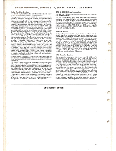
>> Download sx30 p25 documenatation <<
Text preview - extract from the document
Audio Amplifier      Section                                         SRX   29-SRX     30 Receiver    sections
The circuit diagram shows the complete circuit and is drawn          The AM and FM tuner sections       are quite separate;   consider
so that the various sections are clearly identified.                 firstthe AM section:
P.U. signals are amplified by TR 501-504 which also provide
                                                                     The two-section tuning gang tunes simultaneously the iocal
frequency response correction (RIAA) for magnetic .cart-
                                                                     oscillator and selected aerial coil, aerial signal current is
ridges, the resulting signal then passes through to the Input
                                                                     picked up by mutual coupling to the tuned coil and fed into a
selector switch bank (Sl, S2, S3). Signals from other sources,
                                                                     RF amplifier/ AGC stage TR 401 whose output feeds the local
i.e. Tape and Radio, are also fed into these switches which
                                                                     oscillator-mixer input to generate an IF of 470kHz. All IF filter-
enable the desired signal to be channeled into the tone control
                                                                     ing is provided by R 419, R 420, C 427 and C 429. Audio signals
stage. This consists of two "Thick Film" units (MC 483 A & B)
                                                                     are fed from the detector and filter to the amplifier input selec-
which each contain: an emitter follower, followed by a voltage
                                                                     tor switch bank (S1, S2, S3).
amplifier, followed by a second emitter follower; a Baxandall
type feedback tone control circuit is connected to the voltage
amplifier which also provides a phase-shift type scratch filter.     VHFjFM     Section
The second emitter follower has "boot-strapping"        from its
emitter to its base. This network is switchable and provides a       VHF aerial signals are fed directly to the RF amplifier built into
steep-slope rumble filter giving sharp attenuation below 40Hz.       the LP 1186 tuner module, which is a factory pre-aligned unit,
Volume and balance controls follow on to control signal levels       providing RF amplification, local oscillator and mixer stages to
into the main amplifiers. These consist of D.C. coupled              generate a 10
◦ Jabse Service Manual Search 2026 ◦ Jabse Pravopis ◦ onTap.bg ◦ Other service manual resources online : Fixya ◦ eServiceinfo