Service Manuals, User Guides, Schematic Diagrams or docs for : . Rare and Ancient Equipment MYSTERY Car Audio Mystery MMTD-9200s Mystery MMTD-9200s
<< Back | HomeMost service manuals and schematics are PDF files, so You will need Adobre Acrobat Reader to view : Acrobat Download Some of the files are DjVu format. Readers and resources available here : DjVu Resources
For the compressed files, most common are zip and rar. Please, extract files with Your favorite compression software ( WinZip, WinRAR ... ) before viewing. If a document has multiple parts, You should download all, before extracting.
Good luck. Repair on Your own risk. Make sure You know what You are doing.
Image preview - the first page of the document
>> Download Mystery MMTD-9200s documenatation <<
Text preview - extract from the document
Contents
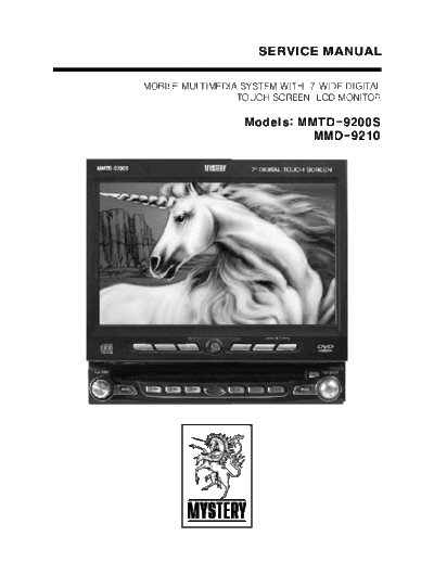
1. Cover
2. Features
3. Block Diagram (Main)
4. Block Diagram (Monitor)
5. Unit Wiring Diagram
6. Schematic Diagram (Main)
7. Schematic Diagram (Monitor)
8. Schematic Diagram (TV BOX)
9. IC & TR Voltage Chart (Main PCB)
10. IC & TR Voltage Chart (Monitor PCB)
11. Exploded View & Part's List (MMTD-9200S)
12. Exploded View & Part's List (Tilt Loader)
13. Exploded View & Part's List (DVD Deck)
14. Circuit Board Diagram (Main)
15. Part's List (MMTD-9200S) Main PCB Ass'y
16. Circuit Board Diagram (Monitor)
17. Part's List (MMTD-9200S) Monitor PCB Ass'y
18. Circuit Board Diagram (Front)
19. Part's List (MMTD-9200S) Front PCB Ass'y
20. Circuit Board Diagram (Tuner)
21. Part's List (MMTD-9200S) Tuner PCB Ass'y
22. Part's List (Tilt Loader) Motor PCB Ass'y
23. Part's List (DVD Deck) MPEG PCB Ass'y
24. Part's List (MMTD-9200S) Packing Ass'y
25. Product Specification
2. Features
o Motorized 7" Digital TFT Screen
o AM/FM Stereo Tuner
o TV Tuner with Diversity Antenna Input
o DVD-R/RW, CD-R/RW Compatible
o Video Select (V Sel.) Rear Zone Output
o ESP - Electronic Shock Protection for DVD, MP3 and CDDA
o OSD - On Touching Screen Display
o Joystick Menu Navigation
o AV1 and AV2 Inputs for System Expansion
o Auto Dimmer Illumination
2
"
5. Unit Wiring Diagram
2
10A
15
13
14
16
Blue
3
17
18
Black
Front
Yellow
FILTER & 4
12 FUSE BOX +
Gray
Rear Black
5
Orange
19
1
Pink
6
TO HEAD UNIT-
Red
7
Antenna Included
White/Black (-) Gray/Black (-)
8
9
White (+) Gray (+)
TY
DIVERSI
OPTIONAL
ANT
Green/Black (-) Violet/Black (-) 1 2 3 4
10 11
Green (+) Violet (+)
5
6. Schematic Diagram (Main)
6 7
7. Schematic Diagram (Monitor)
8 9
◦ Jabse Service Manual Search 2026 ◦ Jabse Pravopis ◦ onTap.bg ◦ Other service manual resources online : Fixya ◦ eServiceinfo