Service Manuals, User Guides, Schematic Diagrams or docs for : . Rare and Ancient Equipment PRINTEX MANUALS Cayenne D Quartz Flash-Manual (24 June 2006)
<< Back | HomeMost service manuals and schematics are PDF files, so You will need Adobre Acrobat Reader to view : Acrobat Download Some of the files are DjVu format. Readers and resources available here : DjVu Resources
For the compressed files, most common are zip and rar. Please, extract files with Your favorite compression software ( WinZip, WinRAR ... ) before viewing. If a document has multiple parts, You should download all, before extracting.
Good luck. Repair on Your own risk. Make sure You know what You are doing.
Image preview - the first page of the document
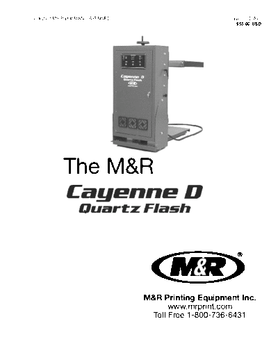
>> Download Cayenne D Quartz Flash-Manual (24 June 2006) documenatation <<
Text preview - extract from the document
V.062405MS Part # MAN-CAYENNED Cayenne D Av2
$55.00 USD
The M&R
M&R Printing Equipment Inc.
www.mrprint.com
Toll Free 1-800-736-6431
i
IMPORTANT!
IMPORTANT!
The product described in this publication may employ hazardous voltages or might create
other conditions that could, through misuse, inattention, or lack of understanding, result in
personal injury, or damage to the product or to other equipment. It is imperative, therefore,
that personnel involved in the installation, maintenance, or use of this product understand
the operation of the product and the contents of this publication.
This document is based on information available at the time of its publication. While efforts
have been made to be accurate, the information contained herein does not purport to cover
all details or variations in hardware, software, features or specifications, nor to provide for
every possible contingency in connection with installation, operation and maintenance.
Features may be described herein which are not present in all variations of this product.
M&R Printing Equipment, Inc. assumes no obligation of notice to holders of this document
with respect to changes subsequently made.
M&R Printing Equipment, Inc. makes no representation or warranty, expressed, implied or
statutory with respect to, and assumes no responsibility for the accuracy, completeness,
sufficiency or usefulness of the information contained herein. No warranties of
merchantability or fitness for purpose shall apply.
A publication of M&R Printing Equipment, Inc. All information contained herein is derived in part from proprietary and
patent data of M&R Printing Equipment, Inc. This publication may not be reproduced, copied, or transmitted in any form
without prior permission from M&R Printing Equipment, Inc. Printed in the U.S.A. All Rights Reserved. 2003.
Equipm
nting en
Pri t,
R
M&
Inc
.
rk
W or
wo
ld w
et
de
N
i
Te ce
c h n ic al S e r vi
Valued Customer,
Thank you and congratulations on your purchase of the new Cayenne D Flash unit.
The Cayenne D Flash is the latest addition to M&R's line-up of economic and energy efficient flash cure
systems, and is the perfect companion for M&R's manual and automatic textile presses. Designed to
flawlessly integrate with your M&R press, Cayenne D Flash uses state-of-the-art quartz tubes for rapid
flash curing during high-speed production. Your Cayenne D Flash features a solid state digital controller
that provides single point adjustment for temperature, exposure time, selective quartz heating element
zone activation and power output setting. The Cayenne D automatically reverts to standby mode when
your press is idle. The chassis is rugged, and fully portable, with floor leveling pads for ease of setup.
A thorough understanding of the operation and maintenance of your new Cayenne D Flash will insure
maximum production rates and a long service life for your investment. This operator's manual is provided
to help guide you, and your employees, in the proper procedures for set-up, operation and preventive
maintenance of your new Cayenne D Flash unit.
Should you have any questions regarding the operation or maintenance of your new Cayenne D Flash,
M&R's world wide technical service and support network is available to you during regular business hours
(8:30 a.m. - 5:00 p.m. CST) at 1-800-736-6431, or, on weekends or holidays, call our 24-hour Emergency
Service Hotline at 1-630-462-4715 for technical support 24 hours a day, seven days a week.
On behalf of all of us here at M&R, thank you for selecting us as your equipment supplier.
Michael J. Sweers
Director of Technical Services
M&R Printing Equipment, Inc.
Table of
Disclaimer
Contents Model Description
Introduction
Safety Precautions................................................1
Safety Precautions & Specifications........................................................5
Equipment Views...................................................6
Specifications Assembly ..............................................................7
Installation Instructions..........................................9
Installation & Control & Adjustments.........................................12
Operation
Trouble Shooting Preventive Maintenance......................................13
Troubleshooting Procedure.................................21
Preventive Maintenance
Replacement Parts and Replacement Parts..............................................25
Warranty Information...........................................
Warranty Information
Safety Precautions
SAFETY PRECAUTIONS Nationally Recognized Testing Laboratories, such as
FUNDAMENTAL SAFETY INSTRUCTIONS: Underwriters Laboratories in the United States, and
Please read all information regarding safety the European Economic Community (CE) Standards
precautions as presented in the Operator's and Directives. However, it is possible that
Manual. dangerous conditions which can cause serious injury
The fundamental requirement to assure safe and or loss of life for the user or third persons, or damage
trouble-free operation of this equipment, is a to the equipment or property could occur. This
thorough understanding of the safety information equipment must be used only for the defined
contained in this Operator's Manual. This Operator's purpose as described in the Operator's Manual, and
Manual includes important instructions to assure must be maintained in perfect running condition in
safe operation of this equipment. This Operator's accordance with described Safety Regulations.
Manual, and especially the safety instructions as Conditions which may compromise operator safety
described there-in, must be observed by everyone must be identified and corrected immediately.
who will operate this equipment. In addition to the
safety instructions and regulations described in this Defined Purpose:
Operator's Manual, rules and regulations of the The M&R Cayenne D Flash unit is specifically
equipment owners place of business must also be designed to cure/dry textile inks on textile
observed. substrates. Any other use of the equipment which
does not meet the Defined Purpose as described
Obligation of the Equipment Operator: above is not permitted. In accordance with the
The equipment Operator is obliged to guarantee that Defined Purpose of this equipment, it is necessary to
only staff who are acquainted with the fundamental observe all instructions as outlined in the Operator's
regulations according to workers protection and Manual and to perform the preventive maintenance
accident prevention, and, are completely procedures as described in the manual.
knowledgeable in the operation of this equipment
have fully read the Safety Chapter and the Warning Guarantee and Liability:
Instructions of this manual, and understand the In principle, our general terms of sale and delivery are
instructions as they relate to operation of this valid and these are at the Operator's disposal.
equipment. Equipment Operators must be Guarantee and liability claims for persons or property
continually evaluated to assure that they fully damage are excluded if they originate for one or
understand the operation of this equipment. more of the following reasons.
Obligation of Personnel: 1. A non-defined use of the equipment
Every person that will be engaged in the operation of 2. Improper installation or use of the equipment
this equipment must comply with the following 3. Operation of the equipment with defective safety
before operation of the equipment is to begin. devices.
1. Observe the fundamental regulations of 4. Non-Observance of instructions as described in
worker's protection and accident prevention. the Operator's Manual for transportation, storage,
2. Read the Safety Chapter and Warning installation, operation, maintenance, set-up and
Instructions of this Operator's Manual and confirm take-down of the equipment.
by signature that they understand the instructions 5. Modification of the equipment.
as described in the manual. 6. Failure to replace worn or defective parts of the
equipment.
Dangerous Situations during Operation of 7. Defective repairs made to the equipment.
the Equipment: 8. Dangerous conditions which are a result of the
The M&R has been designed and constructed in improper use of the equipment.
accordance with safety standards as described by
M&R Printing Equipment, Inc. Glen Ellyn, Illinois 60137 U.S.A. 1
Safety Precautions
Description of Safety Symbols and This symbol is used to
Instructions: describe operating tips or
especially useful information.
This symbol signifies or alerts This information will enable
the equipment operator of the Operator to use all
conditions or areas of the equipment functions for
equipment which present
OPERATING optimal performance.
imminent danger to the health TIP!
of the equipment Operator.
DANGER! Non-observance of these
instructions has serious Organizational Measures:
health consequences, and Equipment operators are responsible to provide
can lead to highly personal protection when operating this equipment.
dangerous injuries. All safety devices must be checked each day before
operation of the equipment can begin.
Safety Devices:
This symbol signifies a Before beginning operation of the equipment, all
possible imminent danger for safety appliances must be checked for proper
life and health of persons and operation.
equipment Operators. Safety devices may only be removed after.....
Non-observance of these
instructions can have 1. The equipment is shut down.
2. The electrical power has been dis-connected from
WARNING! serious health
the equipment.
consequences and can lead
to highly dangerous injuries. 3. In case of delivery of partial components, the
Operator must install safety devices in
accordance with regulations.
This symbol signifies a
possible danger. Exploratory Safety Measures:
Non-observance of these The Operator's Manual must be kept on or near the
instructions can lead to light equipment at all times. All safety and danger notices
injuries or damage to the must be kept in readable condition at all times.
equipment or property.
Training of Equipment Operator's
CAUTION! Only properly trained operators may run the equipment.
The competence of personnel who are to operate,
maintain, set-up and shut down the equipment must be
confirmed. Unskilled staff may work with the equipment
This symbol gives important only when supervised by experienced equipment
i
instructions for the proper use Operators.
of the equipment.Non-
observance of these Equipment Control System:
instructions can lead to Never make any modifications to software.
equipment failure. Only experienced Operators may actuate the control
IMPORTANT! system.
2 M&R Printing Equipment, Glen Ellyn, Illinois 60137 U.S.A.
Safety Precautions
Safety Measures during Normal Operation: Structural Modification of the Equipment:
Operate the equipment only if all safety devices are Modifications of equipment are specifically not
fully operational. Before starting the equipment, allowed with out written authorization from M&R, Inc.
check to be sure no-one will be endangered by the
operation of the equipment. Check the equipment Cleaning of the equipment:
and safety devices at least once per shift for external Clean away all ink or other contaminant's at the end
or visible damage. of each day.
Danger by Electrical Energy: Equipment Noise:
Under normal operating conditions as described
Work on the electrical system under Defined Purpose, this equipment will not
must be carried out by produce sound above the level of 65 db. Depending
qualified personnel only. on local conditions, a higher continuous sound level
Check the electrical may result that could lead to hardness of hearing. In
equipment regularly for any this case, the operational staff must wear appropriate
sign of defect or loose safety clothing or protection.
DANGER! connections.
Electrical enclosures must be CAUTION: The information
kept securely locked at all contained in this Operator's
times. Manual has been provided to
Only authorized personnel eliminate problems from
with a key are allowed access occurring. Be sure to read
to electrical enclosures. through this Operator's
CAUTION! Manual fully before operating
Danger by Pneumatic Energy: your press.
Only personnel with experience with pneumatic There are numerous safety
power systems may work with pneumatic features utilized in the
components or assemblies. Before starting any work operation of this equipment.
on pneumatic components or assemblies, the Please be sure you know the
compressed air supply must be completely location of these safety
drained from the equipment to prevent any devices and how they
operation of pneumatic controls or assemblies. operate before attempting to
All pneumatic piping and/or hoses must be checked operate this equipment.
at regular intervals for signs of wear or failure.
SAFETY FEATURES -
Maintenance & Trouble Shooting: 1. All equipment is provided with either a safety bar,
Preventive maintenance must be performed at foot switch, yellow cycle interruption cords, infrared
regular intervals as described in the Operator's safety beam, yellow floor mats or hand switch to
Manual. stop the equipment. Please know the type on your
Equipment operator's must be informed before any equipment and its location and function before
preventive maintenance can be performed. operating.
All power systems such as electrical, pneumatic,
hydraulic or mechanical must be dis-connected
and locked out before preventive maintenance
may begin.
M&R Printing Equipment, Inc. Glen Ellyn, Illinois 60137 U.S.A. 3
Safety Precautions
NEVER ATTEMPT TO BY-PASS equipment consider safety first an important part of
OR DEFEAT ANY SAFETY their job.
DEVICE OR APPLIANCE. IN The following general safety considerations are
THE EVENT THAT ANY OR ALL offered as an aid to users of M&R equipment to
SAFETY DEVICES ARE NOT assist them in becoming safety conscience.
OPERATING OR FUNCTIONING
DANGER! PROPERLY, DO NOT ATTEMPT 1. READ THE OPERATOR'S MANUAL before
TO OPERATE THIS attempting to lift, move, operate or perform
EQUIPMENT! maintenance on any piece of machinery.
2. Safety guards have been provided to protect the Become intimately familiar with all equipment
operator from all moving parts. Please do not controls, their locations, their operation and their
remove these Safety Guards any time the equipment effect on equipment function. Keep this Operator's
is in operation. Manual in a clean location immediately adjacent to
the equipment for a quick and handy reference.
3. This Operator's Manual includes information
regarding the proper preventative maintenance 2. BEFORE ATTEMPTING TO START THE
procedures. When ever personnel are performing EQUIPMENT inspect all areas around and adjacent
preventative maintenance procedures, be sure that to moving parts for possible obstructions: tools,
all electrical and pneumatic power is rags, crating remnants etc. Be certain that all Safety
disconnected from the equipment, and that Guards, covers, access doors etc., are properly
disconnects are locked in the "OFF" position. installed prior to starting operation.
4. Never work on the table surface under the print 3. PRACTICE GOOD HOUSEKEEPING: Maintain
stations unless the power "ON/OFF" switch is and area adjacent to NOT ON the equipment for tool
placed in the "OFF" position. and garment storage. Clean up all spills and
eliminate all potential trip points from the operating
OPERATOR SAFETY INSTRUCTIONS - areas around the equipment to prevent slipping or
All industrial equipment, including packaging falling into the working zone of the equipment. Do
equipment, requires a combination of high electrical, not stand on equipment elements not intended
pneumatic, hydraulic or mechanical power for for this purpose. Maintain a maximum clear area
operation. In addition, automatic packaging around the equipment for unobstructed movement of
equipment, by its nature, exposes operators to parts the Operator. Perform Preventative Maintenance at
and assemblies which operate at high speeds and the intervals specified in this Operator's Manual.
contain numerous moving parts. As with all complex
industrial equipment, care should be exercised to 4. AVOID WEARING LOOSE CLOTHING , long hair,
carefully observe proper operating procedures and neck ties etc., when operating this equipment as
safety precautions. these can easily become entangled in moving parts.
Safety shoes are likewise recommended. Avoid
Although every effort has been made to design and horseplay around the equipment.
construct safe, dependable equipment, it is
impossible to foresee all circumstances under which 5. DO NOT ATTEMPT to operate this equipment if
this equipment may be utilized, or to anticipate all you are sick, excessively fatigued or under the
possible combinations of factors which may cause a influence of alcohol or prescription drugs. Shut off
hazardous condition or situation. It is therefore the equipment immediately if any malfunction occurs
imperative that the equipment Operator, as well as or appears imminent. Report any unsafe equipment
all other personnel engaged in any phase of the set- or condition promptly in order that correction can be
up, operation or preventative maintenance of this made as soon as possible.
4 M&R Printing Equipment, Glen Ellyn, Illinois 60137 U.S.A.
Safety Precautions
6. BY-STANDERS should stay well away from the
equipment so as not to distract the operator or Compressed Filament
accidentally move a control element. Avoid talking to
the operator while the equipment is in operation.
7. WHEN CHANGING SET-UP, performing
maintenance work, cleaning the equipment etc., it is
imperative that the main electrical and pneumatic
power supplies be disconnected to avoid accidental
operation and possible resultant injury. This is
particularly important in the event more than one
person is involved in such duties.
8. A WRITTEN SAFETY PROGRAM should be
installed by all companies owning M&R Equipment.
This program should cover inspection, maintenance
and safety training on the proper use of the
machinery.
WARNING! DO NOT
AT T E M P T T O O P E R AT E
THE EQUIPMENT UNLESS
ALL SAFETY PRECAUTIONS
HAVE BEEN OBSERVED!
WARNING!
WARNING! NEVER OPERATE THE
CAYENNE D FLASH UNIT IF THE
FLASH UNIT IS PLACED ON ITS'
SIDE FOR ANY REASON. IN THIS
POSITION THE QUARTZ HEATING
ELEMENT FILAMENTS WILL
COMPRESS DUE TO GRAVITY
WARNING! AND WILL ARC RESULTING IN
PREMATURE FAILURE OF THE
ELEMENT FILAMENT. ALWAYS
OPERATE THE TACANA FLASH
WITH THE QUARTZ HEATING
ELEMENTS IN THE HORIZONTAL
(NORMAL OPERATING POSITION)
POSITION. (See illustration above
right)
M&R Printing Equipment, Inc. Glen Ellyn, Illinois 60137 U.S.A. 5
Safety Precautions
NOTES:
6 M&R Printing Equipment, Glen Ellyn, Illinois 60137 U.S.A.
Specifications
Size Electrical Requirements Size Electrical Requirements
18" x 18" 208/230VAC, 3 phase, 31/34 amps, 11.1 Kw 24" x 30" 208/230VAC, 3 phase, 42/43 amps, 15.1 Kw
240VAC, 3 phase, 35 amps, 14.5 Kw 240VAC, 3 phase, 48 amps, 19.9 Kw
380VAC, 3 phase, 18 amps, 11.8 Kw 380VAC, 3 phase, 25 amps, 16.4 Kw
415VAC, 3 phase, 20 amps, 14.3 Kw 415VAC, 3 phase, 27 amps, 19.3 Kw
480VAC, 3 phase, 16 amps, 13.2 Kw 480VAC, 3 phase, 23 amps, 19.1 Kw
18" x 22" 208/230VAC, 3 phase, 31/34 amps, 11.1 Kw 24" x 36" 208/230VAC, 3 phase, 50/53 amps, 17.1 Kw
240VAC, 3 phase, 35 amps, 14.5 Kw 240VAC, 3 phase, 55 amps, 22.8 Kw
380VAC, 3 phase, 18 amps, 11.8 Kw 380VAC, 3 phase, 28 amps, 18.4 Kw
415VAC, 3 phase, 20 amps, 14.3 Kw 415VAC, 3 phase, 31 amps, 22.2 Kw
480VAC, 3 phase, 18 amps, 13.2 Kw 480VAC, 3 phase, 27 amps, 22.4 Kw
22" x 24" 208/230VAC, 3 phase, 31/34 amps, 11.1 Kw 38"x48"T 208/230VAC, 3 phase, 85/94 amps, 30.5 Kw
240VAC, 3 phase, 35 amps, 14.5 Kw 240VAC, 3 phase, 97 amps, 40.2 Kw
380VAC, 3 phase, 18 amps, 11.8 Kw 380VAC, 3 phase, 52 amps, 34.1 Kw
415VAC, 3 phase, 20 amps, 14.3 Kw 415VAC, 3 phase, 56 amps, 40.2 Kw
480VAC, 3 phase, 16 amps, 13.2 Kw 480VAC, 3 phase, 49 amps, 40.6 Kw
22" x 24" 208/230VAC, 3 phase, 34/37 amps, 10.0 Kw 40" x 32" 208/230VAC, 3 phase, 86/94 amps, 30.9 Kw
240VAC, 3 phase, 38 amps, 15.7 Kw 240VAC, 3 phase, 98 amps, 40.6 Kw
380VAC, 3 phase, 20 amps, 13.5 Kw 380VAC, 3 phase, 52 amps, 34.1 Kw
415VAC, 3 phase, 22 amps, 15.7 Kw 415VAC, 3 phase, 57 amps, 40.9 Kw
480VAC, 3 phase, 19 amps, 15.7 Kw 480VAC, 3 phase, 50 amps, 41.5 Kw
22" x 30" 208/230VAC, 3 phase, 39/43 amps, 14.0 Kw 40"x36"T 208/230VAC, 3 phase, 74/82 amps, 26.6 Kw
240VAC, 3 phase, 45 amps, 18.6 Kw 240VAC, 3 phase, 85 amps, 35.2 Kw
380VAC, 3 phase, 24 amps, 15.7 Kw 380VAC, 3 phase, 47 amps, 30.9 Kw
415VAC, 3 phase, 26 amps, 18.6 Kw 415VAC, 3 phase, 51 amps, 36.6 Kw
480VAC, 3 phase, 23 amps, 19.1 Kw 480VAC, 3 phase, 43 amps, 35.7 Kw
22" x 36" 208/230VAC, 3 phase, 50/56 amps, 17.9 Kw 40" x 36" 208/230VAC, 3 phase, 87/94 amps, 31.3 Kw
240VAC, 3 phase, 58 amps, 24.0 Kw 240VAC, 3 phase, 99 amps, 41.1 Kw
380VAC, 3 phase, 30 amps, 19.7 Kw 380VAC, 3 phase, 53 amps, 34.8 Kw
415VAC, 3 phase, 33 amps, 23.6 Kw 415VAC, 3 phase, 58 amps, 41.6 Kw
480VAC, 3 phase, 28 amps, 23.2 Kw 480VAC, 3 phase, 50 amps, 41.5 Kw
The electrical specifications indicated are based on mathematical calculations which assume
i
ideal conditions exist for electrical supply line values, material used in the installation of
electrical service and site preparation. Although every effort has been made to provide accurate
electrical specifications, M&R Printing Equipment, Inc., does not assume any liability for
damages, whether consequential or incidental, that may result from the use of the indicated
electrical specifications. M&R Printing Equipment, Inc.,encourages the use of a licensed
IMPORTANT Electrician for the installation of electrical service to this equipment. The equipment when
installed must be electrically grounded in accordance with local codes, or in the absence of local
codes, with the National Electrical Code ANSI/NFPA 70- Latest Edition.
M&R Printing Equipment, Inc. reserves the right to alter specifications in the manufacture of its
products.
M&R Printing Equipment, Inc. Glen Ellyn, Illinois 60137 U.S.A. 7
Spare Parts & Recommended Hand Tools
Recommended Spare Parts
Quantity Description Part No.
3 Quartz heating elements Order by model
4 Air filter elements 1009012
1 2-Position toggle switch 1010011
1 2-Pole toggle switch 1010007
2 Red neon indictor lights 1013000
1 Digital Controller 1012181
2 Current sensor 1024000
1 Solid State Relay 75 amp 1011205
1 Toggle Switch 1010003
1 Thermoswitch 1012022
Recommended Hand Tools
1 - Set standard size Allen wrenches
1 - Standard blade screw driver
1 - Standard Phillips screw driver
1 - 10" adjustable wrench
1 - Set open end wrenches
1 - Volt/Ohm meter (multi-tester)
1 - Wire stripper/solder less terminal crimping tool
1 - 9" torpedo level
8 M&R Printing Equipment, Inc. Glen Ellyn, Illinois 60137 U.S.A.
Elevation
Front of unit. Back of unit.
Right side of unit. Left side of unit.
M&R Printing Equipment, Inc. Glen Ellyn, Illinois 60137 U.S.A. 9
Specifications
NOTES:
10 M&R Printing Equipment, Inc. Glen Ellyn, Illinois 60137 U.S.A.
Installation Procedure
The Cayenne D Flash unit is shipped in one crate, ready for
installation. Carefully uncrate the Cayenne D Flash unit
and examine it for any signs of damage which may have
occurred in transit. M&R is not responsible for any damage
which occurs in transit. Should you discover any damage
to the unit after delivery to you, contact the freight
forwarder immediately to file a damaged goods claim.
Additionally, contact M&R's Customer Service department
at 1-630-858-6101 so that replacement parts may be
identified and ordered.
The crate contains the Cayenne D Flash unit, one carton
which contains the quartz heating elements, and one
carton which contains the signal cable and required Unlock the front frame holder assembly on the print head
assembly hardware. If the Cayenne D Flash unit is to be and secure it in the locked upright position.
installed on an M&R press which is not pre-wired for
integration into the presses PLC system, then an
additional carton will be enclosed which contains the
remote control box, floor stand with sensor assembly and
associated communication cables.
After removing the unit from the crate, install the two rear
leveling legs with plastic adjustment handles and leveling
pads as shown in the illustration below. The threaded
studs with adjustment handle are screwed into the
threaded hole on the lower leveling angle brackets on the
chassis, and then into the metal leveling pad which rests
on the floor.
Move the Cayenne D Flash into position using the chassis
mounted casters provided for this purpose.
Adjustment handle with threaded stud
Leveling pad
Determine which print station you will use for the
location of the Cayenne D Flash. Place that print station
in the rear position by using the "Front/Rear" toggle Leveling the Cayenne D Flash
switch on the control panel. (See illustration top right) The Cayenne D Flash will produce excellent curing results
when leveled properly. It is imperative that the quartz
heating element array be parallel to the pallet surface. The
preferred dimension between the surface of the heating
elements and the pallet surface is 2-1/4" at all four
corners. (See illustration top left next page)
M&R Printing Equipment, Inc. Glen Ellyn, Illinois 60137 U.S.A. 11
Installation Procedure
2. To adjust the front to rear angle of the heating element
Dimension is 2-1/4" from heating element to pallet surface. assembly, loosen the 3/4" hex head bolt located on
either side of the chassis.
Leveling the Cayenne D Flash is easily accomplished by
use of the two rear leveling legs and the front to rear 3. Adjust the front to rear angle by using a 3/4" socket
pivoting adjustment for the heating element assembly. wrench to adjust the hex head bolt located at the
Once the Cayenne D Flash is parallel to the pallet, the bottom center of the chassis. Additional leveling
height or distance from the pallet is easily adjusted by use adjustments are made by alternately adjusting the two
of the hand wheel located at the top of the unit. rear leveling legs located at the rear bottom of the
chassis.
4. When leveling adjustments are completed, tighten the
To level the Cayenne Flash:
3/4" pivot hex head bolts and the rear leveling leg
adjustments.
1. Place a carpenter's level on top of the quartz heating
element assembly to check level both front to back
and side to side. Heating Element Installation
The Cayenne Flash uses a spring-loaded type heating
element. The most common type used in the small to
mid-sized units is the spring loaded lamp connection.
The mechanical type is used on the larger size units.
12 M&R Printing Equipment, Inc. Glen Ellyn, Illinois 60137 U.S.A.
Installation Procedure
Note: The quartz lamp envelope Position one end of the heating element over the spring
i
(glass tube) must always be clean loaded male pin connector on the reflector assembly
of any dirt, oils, or other and carefully push the female electrical connector onto
contaminant's which will lead to the male pin connector. Compression of the spring-
reduced curing efficiency. Always loaded male fixture will require only light (1-2 pounds)
handle heating elements while pressure to properly position the heating element.
IMPORTANT! wearing lint less gloves. Lint less
gloves will prevent the natural oils 3. Bring the opposite end of the heating element into con-
present on your hands from tact with the male pin contact on the other side of the
contaminating the quartz envelope. reflector assembly. Allow the spring-loaded pressure
Before installation, lightly wipe the from the opposite contact to hold the heating element
quartz envelope surface with a lint in position.
less cloth dampened in Isopropyl
Alcohol to remove dirt, oils and 4. Install the remaining heating elements as described
contaminates. above.
The following will explain how to install the spring-loaded When replacing the spring-loaded lamp:
heating elements:
1. Disconnect electrical power from the Cayenne D
1. While wearing lint less gloves, gently grasp the heating Flash.
element at both ends at the electrical connector.
2. Remove the old lamp by grasping the lamp connection
Reflector mounted Male pin contact. at each end of the lamp. Gently move/push the lamp
either to the right or left to compress the spring loaded
female fixture in the reflector assembly.
Light pressure is needed to disengage the lamp.
Slightly lower the lamp 2-3 inches and disengage the
lamp from the opposite male fixture to completely
remove the lamp from the reflector assembly.
3. Using a lint less cloth dampened with Isopropyl Alcohol,
gently wipe the reflector surface to remove any dirt or
contamination which may reduce reflector efficiency.
Gently push female lamp contact onto spring loaded male contact.
4. Check the replacement lamp to be sure both contact
2. The heating element has a female electrical connection retaining clips are properly seated. If either of the
at both ends. This connector is designed to fit over the retainer clips are loose when the lamp is installed in the
corresponding male connector located in the heating reflector connections, the lamp may create an electrical
element mounting socket located on the reflector arc during operation destroying the connector and
assembly. lamp.
5. Lightly wipe the surface of the replacement lamp with
Isopropyl Alcohol to remove any dirt or contamination
which may reduce lamp efficiency.
6. Position the female connector on one end of the lamp
with the spring loaded male connector on the reflector
assembly, and lightly push the lamp onto the connector.
Now, position the other end of the lamp so that the
female contact aligns with the male contact in the
reflector assembly, and gently move the lamp onto the
M&R Printing Equipment, Inc. Glen Ellyn, Illinois 60137 U.S.A. 13
Installation Procedure
contact. The spring loaded contacts will now hold the 4. While wearing lint less gloves, position the replacement
lamp in place. Check to be sure the lamp is secure in lamp so that the white reflective material on the inside
the connector. If the lamp is loose, check the of the lamp envelope is positioned at the top, towards
connectors on both the lamp and the reflector to be the reflector assembly. Install the lamp so the slots on
sure they are not loose or damaged in their mounting. each side of the lamp engage and fit over the threaded
posts. Install the 8/32" nut on each post and tighten
The larger size quartz heating elements employ a securely. Torque to 25 lbs/inches. The replacement
mechanical type electrical connection for mounting of the lamp is now properly installed.
heating elements. Heating elements are held in place by
means of a threaded post and nut. Close examination of To facilitate the installation of the quartz heating elements,
these type of heating elements will reveal an internal the chassis of the Cayenne D Flash may be carefully
material which is used to increase element efficiency by placed and supported on its side.
providing an additional reflective surface. When properly
mounted, this reflective material will be at the top of the
element next to the reflector assembly.
White reflective material.
While wearing lint less gloves, position the heating
element so that the internal white reflective material is
positioned at the top towards the reflector assembly.
Install the heating element so that the slots on each end NEVER POWER UP THE CAYENNE
i
of the heating element engage and fit over the threaded FLASH WITH THE QUARTZ
posts. Install the 8/32" stainless steel nuts on each HEATING ELEMENTS IN THE
mounting post and tighten the nuts securely. VERTICAL POSITION. IN THE
VERTICAL POSITION, THE QUARTZ
To replace the mechanical type lamp: HEATING ELEMENTS ARE
IMPORTANT! EXPOSED TO EXCESSIVE
1. Disconnect the electrical power from the Cayenne D STRESSES WHICH WILL RESULT IN
Flash. ELEMENT FAILURE. ALWAYS MAKE
SURE THE QUARTZ HEATING
2. Remove the old lamp/lamps by loosening 8/32" nut at ELEMENTS ARE IN THE NORMAL
either end of lamp connection. Slightly lower the lamp HORIZONTAL POSITION BEFORE
2-3 inches until the ends clear the threaded mounting POWERING UP THE CAYENNE
post, then completely remove the lamp from the FLASH.
reflector assembly.
Double check to be sure all heating elements are securely
3. Using a lint less cloth dampened in Isopropyl Alcohol, installed in their respective terminals. (See illustration at
gently wipe the reflector surface and replacement lamp top left next page)
to remove any dirt or contamination which may reduce
reflector efficiency.
14 M&R Printing Equipment, Inc. Glen Ellyn, Illinois 60137 U.S.A.
Installation Procedure
Plug the signal cable into the first available socket on the
left. The remaining plugs are provided for future units.
After installation of all quartz heating elements, carefully Note: The Sportsman press is only available with two
place the Cayenne D Flash upright in its normal operating sockets.
position. Supply electrical power to the unit to confirm
element operation. To select PLC for the mode of operation, use the digital
controller. Press F4 twice on the digital controller to
access the "Mode" menu. Now press the "Arrow Up" key
to select PLC or the "Arrow Down key to select "Prox".
located on the Cayenne D Flash unit must be set to "PLC
Signal". If this switch is in any other position, the Cayenne
D Flash unit will not operate.
Proximity Sensor Models
When used in conjunction with a M&R press which does
not include the prewired plug sockets located on the
presses lower electrical enclosure, the Cayenne D Flash
unit is operated and controlled through the use of a
remotely located proximity sensor with stand.(See
illustration below)
Signal Cable Installation
PLC controlled models Sensor
The Cayenne D Flash unit is designed to receive Part No.
operational signals from either the on-board 1010095A
programmable logic controller (PLC) of your M&R press
control system, or from an independent proximity sensor
located beneath the index carousel pallet support arms. Floor Stand
Part No.
In the case of the PLC signal method, you need only install 9P10713
the signal cable from the plug marked "PLC Signal" on the
Cayenne D Flash unit, to the plug socket located on the
presses lower electrical enclosure provided for this
purpose. You will note that there are four plug sockets
located on the press. (See illustration top right)
The remotely located proximity sensor mounted to a floor
stand assembly is utilized to supply the trigger "On" signal
to the Cayenne D Flash unit in this application.
M&R Printing Equipment, Inc. Glen Ellyn, Illinois 60137 U.S.A. 15
Installation Procedure
The following provides information on how to configure WARNING! NEVER OPERATE THE
this type system. TACANA FLASH UNIT IF THE
FLASH UNIT IS PLACED ON ITS'
1. Connect the communication cable on the proximity SIDE FOR ANY REASON. IN THIS
sensor to the plug located on the side of the Cayenne POSITION THE QUARTZ HEATING
D Flash unit. ELEMENT FILAMENTS WILL
COMPRESS DUE TO GRAVITY AND
2. Locate the sensor and floor stand assembly, and posi WARNING! WILL ARC RESULTING IN
tion the floor stand and sensor underneath the index PREMATURE FAILURE OF THE
table pallet at the print station just before the print ELEMENT FILAMENT. ALWAYS
station where the Cayenne D Flash unit is located. The OPERATE THE TACANA FLASH
sensor should be adjusted to read the lower pallet WITH THE QUARTZ HEATING
support arm just as it starts to make an index cycle. ELEMENTS IN THE HORIZONTAL
This provides sufficient time for the Cayenne D Flash (NORMAL OPERATING POSITION)
unit to begin its preheat cycle. POSITION. (See illustration below)
Compressed Filament
Multiple Cayenne D Flash unit installations, which
incorporate the remote sensor control system, may be
controlled in the same manner as described above. A
communication cable is installed from each unit to the
quartz plug socket on the lower index electrical box.
In cases where quartz plug sockets are not available, a
jumper communication cord is used between the Cayenne
flash units to transmit operation signals to each unit.
16 M&R Printing Equipment, Inc. Glen Ellyn, Illinois 60137 U.S.A.
Control Panel
PREHEAT ON/WORK/OFF -
POWER ON/OFF TOGGLE This switch is used to preheat the quartz heater elements when the Cayenne D
SWITCH - Flash unit is initially turned on. Preheat (momentary position) will activate the
Place this toggle switch in the quartz bulbs for the time set on the flash units digital controller, during that preheat
"On" position to supply electrical time the operator may flip the switch to the "OFF" position and it will disconnect
power to the equipment. power to the bulbs, regardless of how much time is left in the preheat countdown.
Work position means that the unit is ready to work in either PLC/PROX modes,
meaning the bulbs will energize when a signal is given to the flash unit from either
the presses PLC, or from a Proximity switch. OFF Position means that the bulbs
cannot receive power or energize regardless of which mode the unit is in, PLC or
PROX modes.
OUTSIDE SECTION - CENTER SECTION -
Located in the middle left area of the control This indicator light, when illuminated, indicates
panel, this red indicator light, when illuminated, that the center bank of quartz heater elements
indicates that the outside bank of quartz heater are operating. When extinguished, the center
elements are "On" and functioning. When this bank of quartz heater elements are not
indicator light is extinguished, the outside bank operating.
of elements are inoperative.
M&R Printing Equipment, Inc. Glen Ellyn, Illinois 60137 U.S.A. 17
Control Panel
DIGITAL CONTROLLER -
This digital controller is used to select temperature, exposure time,
lamp section selection and mode of operation...proximity or PLC. This
controller is also used to select either Fahrenheit of Celsius temperature
display and 50 or 60 Hz. electrical supply frequency. See page 19 for
more detailed information.
RESET PUSH BUTTON - INSIDE SECTION -
When the Cayenne D flash is initially power As described previously with the outside and
"On", the "Reset" push button is used to center section, this indicator light is illuminated
connect the control circuitry to the power or when the inside bank of quartz heater elements
load circuits which operate the quartz lamps. are operating. When extinguished, the inside
bank of heater elements are inoperative.
18 M&R Printing Equipment, Inc. Glen Ellyn, Illinois 60137 U.S.A.
Using the Digital Control Unit
INSTRUCTIONS FOR OPERATION OF CAYENNE Upon pressing the "Reset" push button, the control
FLASH DIGITAL CONTROL UNIT (Patent Pending) will display the current Process Temperature Value
Your M&R Cayenne D Flash Cure Unit features a (PV) on the top line and the current Set Temperature
simple to use alpha/numeric digital control unit Value (SV) on the lower line. (See illustration below)
which is used to control temperature, exposure time,
quartz heating element section use and power
output. Using the control to adjust these parameters
is straight forward and easy. PV
Power Up -
Supply electrical power to the equipment. The
control will display "CAY-d" on top line and "FLASH" SV
on lower line. (See illustration below)
F2 F4
SEL
F1 F3
ENT
F1 is used to set the required temperature. Press F1.
The control will display "tEMP" on the top line and sv
F2 F4
"112.2" the set value temperature on the lower line.
SEL To increase the temperature setting press the "Arrow
F1 F3 Up" key. To decrease the temperature setting press
ENT the "Arrow Down" key. When the control returns to
the stand-by mode, the process value (PV) is
Next, place the "Power On" toggle switch in the
"On" position. The control will display "PrESS" on
top line and "rESET" on the lower line. The control PV
is instructing you to press the "Reset" push button
located to the right of the "Power On" toggle
switch.
SV
F2 F4
SEL
F1 F3
ENT
M&R Printing Equipment, Inc. Glen Ellyn, Illinois 60137 U.S.A. 19
Using the Digital Control Unit
displayed on the upper line in green and the set Using the F3 control key you may select any
value (SV) is displayed on the lower line in orange. combination of sections for operation as curing
The minimum setting allowed is 32 degrees F. and requirements may dictate. (See illustration below)
the maximum is 450 degrees F.
F2 is used to set the exposure time. The exposure
time may be set for a maximum of 10 seconds, or for
PV
a minimum of 0.5 seconds. The display on the lower
line is the current exposure time. To increase the
exposure time, press the "Arrow Up" key. To
decrease the exposure time, press the "Arrow SV
Down" key. (See illustration below)
F2 F4
SEL
PV
F1 F3
ENT
SV
F4 is used to select the power output setting for the
quartz heating elements. The range of power may be
F2 F4
set from a minimum of 1% to a maximum of 100%.
SEL
To set the power output, press the F4 key. The
F1 F3 control will display "POWER" on the top line and the
ENT current power output setting on the lower line. To
increase the power output setting press the "Arrow
Up" key. To decrease the power output setting, press
the "Arrow Down" key. (See illustration below)
F3 is used to select individual, or all three lamp
sections for operation. The quartz heating elements
are arranged in three sections, OUTSIDE, CENTER
and INSIDE. To select the sections you wish to PV
operate, press the F3 key. The control will display
"SECt" on the top line, and O C I on the lower line.
When O C I is displayed it indicates that all three
(Outside, Center and Inside) sections are operating. SV
To select only the Outside section press the F3 key
until the O begins to flash. Now press the "Arrow
Up" key one time. The O will change to a dash "-"
indicating that the Outside section is now F2 F4
inoperative. The control will now display - C I. To SEL
change the Center section, press the F3 key twice
until the C flashes. The press the "Arrow Up" key to F1 F3
change the indication to a dash "-". ENT
20 M&R Printing Equipment, Inc. Glen Ellyn, Illinois 60137 U.S.A.
Using the Digital Control Unit
The F4 key is also used to select the mode of
operation for the Cayenne Flash "D", PLC mode or
Proximity mode. When the "PLC" mode is selected,
the Cayenne Flash will receive its start signal from PV
your presses on-board PLC (programmable logic
controller). When "PrX" mode is selected, the
Cayenne Flash "D" will receive its start signal from
the floor stand mounted proximity switch located SV
beneath the carousel pallet support arms.
Press the F4 key twice. The control will display F2 F4
"ModE" on the upper line, and either "PrX" or SEL
"PLC" on the lower line depending on which mode
is currently selected. To change the mode from F1 F3
"PrX" to "PLC", simply press the "Arrow UP" key to ENT
toggle between the two operation modes. The "PrX"
mode should be selected when the Cayenne Flash is
configured to receive its cycle "On" signal from the
optional proximity switch with stand located on the The Cayenne Flash "D's" digital control may be
floor beneath the indexe◦ Jabse Service Manual Search 2026 ◦ Jabse Pravopis ◦ onTap.bg ◦ Other service manual resources online : Fixya ◦ eServiceinfo