Service Manuals, User Guides, Schematic Diagrams or docs for : . Rare and Ancient Equipment PRINTEX MANUALS Saturn Platinum-Manual (19 Aug 2004)
<< Back | HomeMost service manuals and schematics are PDF files, so You will need Adobre Acrobat Reader to view : Acrobat Download Some of the files are DjVu format. Readers and resources available here : DjVu Resources
For the compressed files, most common are zip and rar. Please, extract files with Your favorite compression software ( WinZip, WinRAR ... ) before viewing. If a document has multiple parts, You should download all, before extracting.
Good luck. Repair on Your own risk. Make sure You know what You are doing.
Image preview - the first page of the document
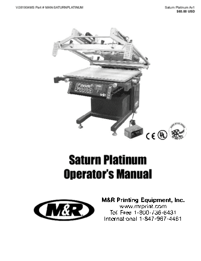
>> Download Saturn Platinum-Manual (19 Aug 2004) documenatation <<
Text preview - extract from the document
V.081904MS Part # MAN-SATURNPLATINUM Saturn Platinum Av1
$65.00 USD
Saturn Platinum
Operator's Manual
M&R Printing Equipment, Inc.
www.mrprint.com
Toll Free 1-800-736-6431
International 1-847-967-4461
i
IMPORTANT!
IMPORTANT!
The product described in this publication may employ hazardous voltages or might cre-
ate other conditions that could, through misuse, inattention, or lack of understanding,
result in personal injury, or damage to the product or to other equipment. It is impera-
tive, therefore, that personnel involved in the installation, maintenance, or use of this
product understand the operation of the product and the contents of this publication.
This document is based on information available at the time of its publication. While
efforts have been made to be accurate, the information contained herein does not pur-
port to cover all details or variations in hardware, software, features or specifications,
nor to provide for every possible contingency in connection with installation, operation
and maintenance. Features may be described herein which are not present in all varia-
tions of this product. M&R Printing Equipment, Inc. (M&R) assumes no obligation of
notice to holders of this document with respect to changes subsequently made.
M&R makes no representation or warranty, expressed, implied or statutory with respect
to, and assumes no responsibility for the accuracy, completeness, sufficiency or use-
fulness of the information contained herein. No warranties of merchantability or fitness
for purpose shall apply.
A publication of M&R Printing Equipment, Inc. All information contained herein is derived in part from proprietary and
patent data of M&R Printing Equipment, Inc. This publication may not be reproduced, copied, or transmitted in any form
without prior permission from M&R Printing Equipment, Inc. Printed in the U.S.A. All Rights Reserved. 2004.
The information listed below will prove helpful when ordering replacement parts,
requesting service or repairs. Please fill in the following information. The Model No.,
Serial No., Schematic No. and Machine No. are all located on the Manufacturers
Rating Plate mounted to the equipment. Should you have any questions regarding
this information, please do not hesitate to contact our Equipment Service
Department at 1-800-736-6431 during normal business hours.
Product Name:
Model No.
Serial No.
Schematic No.
Machine No.
Date of Installation:
Installed By:
Equipm
nting en
Pri t,
R
M&
Inc
.
rk
W or
wo
ld w
et
de
N
ce
i
Te
c h n ic al S e r vi
Valued Customer,
Thank you and congratulations on your purchase of your new Saturn Platinum.
The Saturn Platinum defines the standard for high tolerance printing in a compact press, offering a
level of control and performance previously available only in large expensive presses. Designed for
printing of circuit boards, name plates & panels, backlit graphics, membrane switches, four color
halftone printing, printing on glass and ceramics, the Saturn Platinum is ideal for applications where
absolute precision is critical.
A thorough understanding of the operation and maintenance of your new Saturn Platinum will insure
maximum production rates and a long service life for your investment. This operator's manual is pro-
vided to help guide you, and your employees, in the proper procedures for set-up, operation and pre-
ventive maintenance of your new Saturn Platinum.
Should you have any questions regarding the operation or maintenance of your new Saturn Platinum,
M&R's worldwide Technical Service and Support Network is available to you during regular business
hours (8:30 a.m. - 5:00 p.m. CST) at 1-800-736-6431, or, on weekends or holidays, call our 24-hour
Emergency Service Hotline at 1-630-462-4715 for technical support 24-hours-a-day, seven days a week.
International customers please call +847-967-4461.
On behalf of all of us here at M&R, thank you for selecting us as your equipment supplier.
Michael J. Sweers
Director of Technical Services
M&R Printing Equipment, Inc.
Saturn Platinum
Table of
Disclaimer
Contents Model Description
Introduction
Safety Precautions . . . . . . . . . . . . . . . . . . . . . .1
Safety Precautions and Specifications . . . . . . . . . . . . . . . . . . . . . . . . . .5
Specifications Screen Frame and Image Size . . . . . . . . . . . . .7
Installation Instructions . . . . . . . . . . . . . . . . . .8
Set-Up and Print Control Adjustments . . . . . . . . . . . . . . . .11
Operation Control Panel . . . . . . . . . . . . . . . . . . . . . . . . . .15
E-100 Operator Interface . . . . . . . . . . . . . . . . .17
Sentry Take Off Operation . . . . . . . . . . . . . . . .41
Maintenance and Troubleshooting Procedure . . . . . . . . . . . . . . .43
Troubleshooting Preventive Maintenance Procedure . . . . . . . . .44
Replacement Parts and Replacement Parts . . . . . . . . . . . . . . . . . . . . . .73
Warranty Information
Warranty Information
Saturn Platinum Safety Precautions
FUNDAMENTAL SAFETY INSTRUCTIONS This equipment must be used only for the defined purpose
Please read all information regarding safety precautions as described in the operator's manual, and must be main-
as presented in the operator's manual. tained in perfect running condition in accordance with
described Safety Regulations.
The fundamental requirement to assure safe and trouble-free
operation of this equipment, is a thorough understanding of Conditions which may compromise operator safety must be
the safety information contained in this operator's manual. identified and corrected immediately.
This operator's manual includes important instructions to Defined Purpose
assure safe operation of this equipment. This operator's The Saturn Platinum is specifically designed to apply (print)
manual, and especially the safety instructions as described screen printed inks on flat semi-rigid and rigid substrates.
there-in, must be observed by everyone who will operate Any other use of the equipment which does not meet the
this equipment. In addition to the safety instructions and Defined Purpose as described above is not permitted.
regulations described in this operator's manual, rules and
regulations of the equipment owners place of business In accordance with the Defined Purpose of this equipment,
must also be observed. it is necessary to observe all instructions as outlined in the
operator's manual and to perform the preventive mainte-
Obligation of the Equipment Operator nance procedures as described in the manual.
The equipment operator is obliged to guarantee that only
staff who are acquainted with the fundamental regulations Guarantee and Liability
according to workers protection and accident prevention, In principle, our general terms of sale and delivery are valid
and, are completely knowledgeable in the operation of this and these are at the operator's disposal. Guarantee and lia-
equipment have fully read the Safety Chapter and the bility claims for persons or property damage are excluded if
Warning Instructions of this manual, and understand the they originate for one or more of the following reasons.
instructions as they relate to operation of this equipment.
1. A non-defined use of the equipment
Equipment operators must be continually evaluated to 2. Improper installation or use of the equipment
assure that they fully understand the operation of this 3. Operation of the equipment with defective safety
equipment. devices
4. Non-Observance of instructions as described in the
Obligation of Personnel operator's manual for transportation, storage, installa-
Every person that will be engaged in the operation of this tion, operation, maintenance, set-up and take-down of
equipment must comply with the following before operation the equipment.
of the equipment is to begin. 5. Modification of the equipment.
6. Failure to replace worn or defective parts of the
1. Observe the fundamental regulations of worker's pro- equipment.
tection and accident prevention. 7. Defective repairs made to the equipment.
2. Read the Safety Chapter and Warning Instructions of 8. Dangerous conditions which are a result of the
this operator's manual and confirm by signature that they improper use of the equipment.
understand the instructions as described in the manual.
Description of Safety Symbols and
Dangerous Situations during Operation of the Instructions
Equipment
The Saturn Platinum flatbed press has been designed and This symbol signifies or alerts the
constructed in accordance with safety standards as equipment operator of conditions
described by Nationally Recognized Testing Laboratories, or areas of the equipment which
such as Underwriters Laboratories in the United States, and present imminent danger to the
the European Economic Community (CE) Standards and health of the equipment operator.
Directives. However, it is possible that dangerous condi- Non-observance of these
tions which can cause serious injury or loss of life for the instructions has serious health
user or third persons, or damage to the equipment or prop- DANGER! consequences, and can lead to
erty could occur. highly dangerous injuries.
Glen Ellyn, Illinois 1
Safety Precautions Saturn Platinum
This symbol signifies a possible Exploratory Safety Measures
imminent danger for life and health The operator's manual must be kept on or near the equip-
of persons and equipment opera- ment at all times. All safety and danger notices must be kept
tors. Non-observance of these in readable condition at all times.
instructions can have serious
health consequences and can
Training of Equipment Operator
lead to highly dangerous injuries.
WARNING! Only properly trained operators may run the equipment. The
competence of personnel who are to operate, maintain, set-
up and shut down the equipment must be confirmed.
This symbol signifies a possible
Unskilled staff may work with the equipment only when
danger. Non-observance of these
supervised by experienced equipment operators.
instructions can lead to light
injuries or damage to the equip-
ment or property. Equipment Control System
Never make any modifications to software. Only experi-
enced operators may actuate the control system.
CAUTION!
Safety Measures during Normal Operation
This symbol gives important Operate the equipment only if all safety devices are fully
i
instructions for the proper use of operational. Before starting the equipment, check to be
the equipment. Non-observance sure no-one will be endangered by the operation of the
of these instructions can lead to equipment. Check the equipment and safety devices at
equipment failure. least once per shift for external or visible damage.
Danger by Electrical Energy
IMPORTANT! Work on the electrical system must
be carried out by qualified person-
This symbol is used to describe nel only. Check the electrical equip-
operating tips or especially useful ment regularly for any sign of defect
information. This information will or loose connections. Electrical
enable the operator to use all enclosures must be kept securely
equipment functions for optimal locked at all times. Only authorized
performance. personnel with a key are allowed
OPERATING access to electrical enclosures.
DANGER!
TIP!
Danger by Pneumatic Energy
Organizational Measures Only personnel with experience with pneumatic power sys-
Equipment operators are responsible to provide personal tems may work with pneumatic components or assemblies.
protection when operating this equipment. All safety Before starting any work on pneumatic components or
devices must be checked each day before operation of the assemblies, the compressed air supply must be com-
equipment can begin. pletely drained from the equipment to prevent any oper-
ation of pneumatic controls or assemblies.
Safety Devices
Before beginning operation of the equipment, all safety All pneumatic piping and/or hoses must be checked at reg-
appliances must be checked for proper operation. Safety ular intervals for signs of wear or failure.
devices may only be removed after:
Maintenance and Troubleshooting
1. The equipment is shut down. Preventive maintenance must be performed at regular inter-
2. The electrical power has been disconnected from the vals as described in the operator's manual. Equipment
equipment. operator's must be informed before any preventive mainte-
3. In case of delivery of partial components, the operator nance can be performed.
must install safety devices in accordance with regulations.
All power systems such as electrical, pneumatic,
hydraulic or mechanical must be dis-connected and
locked out before preventive maintenance may begin.
2 Glen Ellyn, Illinois
Saturn Platinum Saturn Platinum
Structural Modification of the Equipment OPERATOR SAFETY INSTRUCTIONS
Modifications of equipment are specifically not allowed with All industrial equipment, including screen printing equip-
out written authorization from M&R ment, requires a combination of high electrical, pneumat-
ic, hydraulic or mechanical power for operation. In addi-
Cleaning of the equipment tion, automatic screen printing equipment, by its nature,
Clean away all ink or other contaminant's at the end of exposes operators to parts and assemblies which operate
each day. at high speeds and contain numerous moving parts. As
with all complex industrial equipment, care should be
Equipment Noise exercised to carefully observe proper operating proce-
dures and safety precautions.
Under normal operating conditions as described under
Defined Purpose, this equipment will not produce sound
Although every effort has been made to design and con-
above the level of 65 db. Depending on local conditions, a
struct safe, dependable equipment, it is impossible to fore-
higher continuous sound level may result that could lead to
see all circumstances under which this equipment may be
hardness of hearing. In this case, the operational staff must
utilized, or to anticipate all possible combinations of factors
wear appropriate safety clothing or protection.
which may cause a hazardous condition or situation. It is
therefore imperative that the equipment operator, as well as
CAUTION: The information con-
all other personnel engaged in any phase of the set-up,
tained in this operator's manual has
operation or preventative maintenance of this equipment
been provided to eliminate prob-
consider safety first an important part of their job.
lems from occurring. Be sure to
read through this operator's manu-
The following general safety considerations are offered as
al fully before operating your press.
an aid to users of M&R to assist them in becoming safety
conscience.
CAUTION! There are numerous safety features
utilized in the operation of this
1. Read the operator's manual before attempting to lift,
equipment. Please be sure you
move, operate or perform maintenance on any piece of
know the location of these safe-
machinery. Become intimately familiar with all equipment
ty devices and how they operate
controls, their locations, their operation and their effect on
before attempting to operate
equipment function. Keep this operator's manual in a clean
this equipment.
location immediately adjacent to the equipment for a quick
and handy reference.
SAFETY FEATURES
1. All equipment is provided with either a safety bar, foot 2. Before attempting to start the equipment, inspect all
switch, yellow safety cords, infrared safety beam, yellow areas around and adjacent to moving parts for possible
floor mats or hand switch to stop the equipment. Please obstructions: tools, rags, crating remnants etc. Be certain
know the type on your equipment and its location and func- that all Safety Guards, covers, access doors etc., are prop-
tion before operating. NEVER ATTEMPT TO BY-PASS OR erly installed prior to starting operation.
DEFEAT ANY SAFETY DEVICE OR APPLIANCE. IN THE
EVENT THAT ANY OR ALL SAFETY DEVICES ARE NOT 3. Practice good housekeeping. Maintain and area adjacent
OPERATING OR FUNCTIONING PROPERLY, DO NOT to NOT ON the equipment for tool and color storage. Clean
ATTEMPT TO OPERATE THIS EQUIPMENT! up all spills and eliminate all potential trip points from the
operating areas around the equipment to prevent slipping or
2. Safety guards have been provided to protect the opera- falling into the working zone of the equipment. Do not
tor from all moving parts. Please do not remove these stand on equipment elements not intended for this pur-
Safety Guards any time the equipment is in operation. pose. Maintain a maximum clear area around the equip-
ment for unobstructed movement of the operator. Perform
3. This operator's manual includes information regarding the Preventative Maintenance at the intervals specified in this
proper preventative maintenance procedures. When ever operator's manual.
personnel are performing preventative maintenance proce-
dures, be sure that all electrical and pneumatic power is 4. Avoid wearing loose clothing, long hair, neck ties etc.,
disconnected from the equipment, and that disconnects when operating this equipment as these can easily become
are locked in the off position. entangled in moving parts. Safety shoes are likewise rec-
ommended. Avoid horseplay around the equipment.
4. Never work on the table surface under the print stations
unless the power "On/Off" switch is placed in the off position.
Glen Ellyn, Illinois 3
Safety Precautions Saturn Platinum
5. Do not attempt to operate this equipment if you are sick,
excessively fatigued or under the influence of alcohol or
prescription drugs. Shut off the equipment immediately if
any malfunction occurs or appears imminent. Report any
unsafe equipment or condition promptly in order that cor-
rection can be made as soon as possible.
6. By-standers should stay well away from the equipment
so as not to distract the operator or accidentally move a
control element. Avoid talking to the operator while the
equipment is in operation.
7. When changing set-up, performing maintenance work,
cleaning the equipment etc., it is imperative that the main
electrical and pneumatic power supplies be disconnected
to avoid accidental operation and possible resultant injury.
This is particularly important in the event more than one per-
son is involved in such duties.
8. A written safety program should be installed by all com-
panies owning M&R Printing Equipment. This program
should cover inspection, maintenance and safety training
on the proper use of the machinery.
WARNING! DO NOT WORK
WITHIN THE INDEX TABLE
OPERATING AREA UNLESS ALL
SAFETY PRECAUTIONS HAVE
BEEN OBSERVED!
WARNING!
4 Glen Ellyn, Illinois
Saturn Platinum Specifications
SPECIFICATIONS
Model Size 15" x 26" (38 x 66 cm) 25" x 38" (64 x 97 cm) 30" x 40" (76 x 102 cm)
208/230v, Single Phase, 14 Amps 208.230v, Single Phase, 14 Amps 208/230v, Single Phase, 14 Amps
Electrical Requirements 380v, Three Phase 8.5 Amps 380v, Three Phase 8.5 Amps 380v, Three Phase 8.5 Amps
Compressed Air Req. 100 P.S.I. @ 3 C.F.M. 100 P.S.I. @ 3 C.,F.M. 100 P.S.I. @ 3 C.F.M.
Shipping Weight 1200 lbs. (544.3 kg) 1400 lbs. (635 kg) 1600 lbs. (726 kg)
Maximum Frame O.D. 32" x 38" x 2.25" (81.2 x 96.5 x 5.7cm) 42" x 50" x 2.25" (106 x 127 x 5.7 cm) 47" x 52" x 2.25" (121 x 133 x 5.7 cm)
Maximum Image Size 15" x 26" (38 x 66 cm) 25" x 38" (64 x 97 cm) 30" x 40" (76 x 102 cm)
Electrical Req. Take-Off 208/230v, 1 phase, 4 Amps 208/230v, 1 phase, 4 Amps 208/230v, 1 phase, 4 Amps
Total Floor Area (Press) 39.25" x 48" (100 x 122 cm) 54.25" x 58" (138 x 147 cm) 54.25" x 63" (138 x 160 cm)
Total Floor Area (Take-Off) 82" x 26" (208 x 66 cm) 86" x 36" (218 x 91 cm) 86" x 41" (218 x 104 cm)
The electrical specifications indicated are based on mathematical calculations which assume
ideal conditions exist for electrical supply line values, material used in the installation of electri-
i
cal service and site preparation. Although every effort has been made to provide accurate elec-
trical specifications, M&R does not assume any liability for damages, whether consequential or
incidental, that may result from the use of the indicated electrical specifications. M&R encour-
ages the use of a licensed Electrician for the installation of electrical service to this equipment.
The equipment when installed must be electrically grounded in accordance with local codes, or
IMPOR- in the absence of local codes, with the National Electrical Code ANSI/NFPA 70- Latest Edition.
M&R reserves the right to alter specifications in the manufacture of its products.
Glen Ellyn, Illinois 5
Specifications Saturn Platinum
A clean, moisture free compressed air supply is essential for the continued oper-
ation of the Saturn Platinum press. We strongly recommend that a refrigerated air
chiller be installed in the compressed air supply line to the Saturn Platinum press
to prevent moisture damage to pneumatic seals, valves and air cylinders used in
the operation of the print carriage (See diagram above). Failure to use a refriger-
ated compressed air chiller with this equipment may void the warranty for pneu-
CAUTION! matic components such as air cylinders, valves and seals.
6 Glen Ellyn, Illinois
Saturn Platinum Screen Frame and Image Size
MODEL No. "A" "B" "C" "D" "E"
SATFB-1526 32" (81.2cm) 38" (96.5cm) 15" (38.1cm) 26" (66.0cm) 8.5" (21.5cm)
SATFB-2538 42" (106.6cm) 50" (127cm) 25" (63.5cm) 38" (96.5cm) 8.5" (21.5cm)
SATFB-3040 47" (119.3cm) 52" (133cm) 30" (76.2cm) 40" (101.6cm) 8.5" (21.5cm)
Glen Ellyn, Illinois 7
Installation Instructions Saturn Platinum
Designed for screen printing small to medium range flexible Operation
and rigid substrates, the Saturn Platinum graphic screen Operation of the Saturn Platinum is rudimentary, and there
printing system offers the graphic screen printer total con- are numerous standard features for optimal production out-
trol of essential print parameters. put for a wide range of applications. Pressure along the
entire length of the squeegee/flood bar assembly is pneu-
Superior control of ink deposition and dot gain are realized matically equalized and maintained for consistent image
through a design which puts the emphasis on superior con- quality. The Saturn Platinum's "whisper quiet" vacuum/blo-
struction and control. The Saturn Platinum's print carriage is back system will accommodate virtually all production
constructed of extruded aluminum for exceptional durabili- requirements and substrate weights. Stock is gently floated
ty. The print carriage design features four roller bearings into position on a cushion of air, held firmly to the bed and
which travel along the top and bottom of a linear steel race- then after completion of the print cycle a gentle puff of air
way to eliminate print carriage chatter and vibration. This efficiently releases the substrate for either stacking by hand
extraordinary print carriage design consistently produces or delivery by the Sentry take-off system.
glass smooth flood and print strokes eliminating erratic ink
deposits while significantly reducing blurred images in The Saturn Platinum is available with the optional Sentry
halftone and process work. take-off system, a fully adjustable gripper style take-off that
will significantly increase your production output. The
Solid-state stroke length sensors permit instant adjustment Sentry operates in combination with stock lift pins perma-
of flood and print stroke for any size screen frame up to the nently mounted in the vacuum bed to lift the stock for
maximum size indicated in the specifications. Simple lock- approach of the take-off.
ing levers and knobs have replaced cumbersome hand
tools to make adjustments to the squeegee/flood bar pres- The Saturn Platinum can also be constructed to add the
sure and angle. Sentry take-off at a later date.
For maximum flexibility, as an option, the Saturn Platinum's Installation
vacuum bed is designed to lower up to 14" (35.5cm) to allow 1. Uncrate your Saturn Platinum and check for any obvious
printing on thicker or three dimensional substrates. Set-up on damage which may have occurred in transit. If damage is
the Saturn Platinum is quick and easy. The master discovered, report this immediately to the freight forwarder.
frame/screen holder is adjustable from both the front and rear M&R is not responsible for damage to equipment which has
of the press and detaches from the raised print head for occurred in transit.
effortless screen loading and unloading. The Saturn Platinum
accepts all screen frame types currently in use, even reten- If it is determined that replacement parts will be required for
sionable frames. Off-contact is easily adjusted at each corner operation of the press, telephone the M&R Service
for a wide range of substrate types or applications. Department at 1-630-858-6101 for assistance.
2. Prepare a location in your shop which will accommodate
the Saturn Platinum press, being sure to leave enough room
for screen frame loading and unloading.
3. Once the press is moved into position, it must be leveled
using the leveling legs provided on the chassis base. A car-
penters level should be placed on the press vacuum bed
running at an angle from corner to corner of the vacuum bed.
8 Glen Ellyn, Illinois
Saturn Platinum Installation Instructions
To level the press, adjust the leveling legs one at a time until 7. The compressed air requirements for the Saturn Platinum
the bed is level from corner to corner, then lock the nuts are 100 PSI @ 3 CFM. An air connection is provided at the
located on each leveling leg to maintain level. rear of the press.
4. After leveling the press, move the Sentry take-off into NOTE: A clean moisture free com-
i
position adjacent to the mounting brackets on the side of pressed air supply is required for
the press. Using the leveling legs on the take-off, adjust the proper operation of this equipment.
take-off height so that the grippers are approximately 1/8" Failure to provide a clean moisture
above the bed when the grippers are fully extended over the free compressed air supply may
vacuum bed. Adjust the two rear take-off support legs so result in premature failure of pneu-
that they are as close to the dryer conveyor chassis as pos- matic components such as seals,
sible. Once the take-off is assembled to the press, place a IMPORTANT! cylinders and valves. Pneumatic com-
carpenters level along the long dimension of the take-off on ponents determined to have failed
both sides and adjust the leveling legs so that the take-off due to failure to supply clean moisture
is level from the front to the rear, then lock the leveling nuts free air to this equipment may not be
located on each leveling leg.) covered under the warranty.
8. The Saturn Platinum's vacuum bed is leveled at the fac-
tory, however some shifting and settling of the bed may
occur during transit. The bed level should be checked and
adjusted if necessary following delivery and set-up.
9. To level the vacuum bed, first lower the print head to the
fully lowered position stopping the print carriage halfway
through the print stroke.
5.The electrical and compressed air connections for the take-
off are located at the lower rear of the press. Remove the rear
access panel to expose the connection panel and run the air
hose and control cables under the press chassis and connect
to the appropriate connecting terminal and port.
6. The electrical requirements for the Saturn Platinum are
110 volts, 1 phase, 20 amps, 60 Hz. for the 25" x 38" model,
and 110 volts, 1 phase, 15 amps, 60 Hz. for the 15" x 26"
model. A standard 100 volt line cord is provided for con-
nection to your 110 volt source.
Glen Ellyn, Illinois 9
Installation Instructions Saturn Platinum
Loosen the registration locking knobs located adjacent to 12. Connect the take-off electrical cable.
the bed so that the support washers are slightly tightened
against the locking plates.
10. Using a square, measure the distance from a point at the
bottom of the aluminum print head carriage extrusion down
to the top of the vacuum bed. Using this dimension as a
standard reference, adjust the under-bed leveling adjust-
ments to level the bed to the standard dimension beginning
with the two front corners. Repeat this procedure with the
two remaining rear corners of the vacuum bed. Finalize the
leveling with a carpenters level.
13. Supply compressed air to the Sentry take-off by con-
necting the air hose. To connect the air hoses together, firm-
ly push the air hose into the compression fitting. You will feel
the air hose seat as you push it into the fitting.
11. After adjusting the four corners, bring the under bed lev-
elers into firm contact with the bed and tighten both the
under-bed leveler nuts and the two locking knobs.
10 Glen Ellyn, Illinois
Saturn Platinum Print Control Adjustments
Central Off-Contact Adjustment
Off-contact is a fundamental component of the screen print-
ing process and has a significant impact on the clarity and
quality of the printed image. Off-contact is defined as the
dimension between the bottom of the screen fabric and the
top surface of the substrate. Insufficient or excessive off-
contact can result in images which are distorted, exhibit
poor edge definition or appear blurred, smeared and/or out
of register.
The Saturn Platinum features a four corner, tool-free "cen-
tral off-contact" adjustment which is designed for ease of
adjustment. Adjustment knobs are conveniently located at
all four corners of the master frame assembly. Turning the
knobs clockwise will increase the off-contact distance while
turning the knobs counter clockwise will decrease the off-
contact distance. For close tolerance printing, the recom-
mended "starting point" off-contact dimension is 1/16"
(1.5mm). This dimension may of course be adjusted to com-
pensate for screen fabric tension.
NOTE: Before using the micro-reg-
Micro Registration Adjustments
i
IMPORTANT!
istration knobs, loosen the locking
knobs at the front and side of the
master frame assembly. Be sure to
tighten the locking knobs after the
image is registered.
To facilitate color to color print register, the Saturn Platinum
includes three micro-registration adjustment knobs located
on the vacuum table base assembly. The center knob Optional Dial Indicator for Micro-Register
moves the vacuum table from side to side or left to right (X
Available as an optional feature are dial indicators which
axis). The knobs on the extreme left and right move the vac-
provide a reference reading as to image position to a toler-
uum table from the front to the rear (Y axis). To adjust the
ance of "+" or "-" .001".
micro-register, first loosen the locking knobs on both the left
and right front and sides of the master frame. Now use the
large aluminum micro-register adjustment knobs to locate
the table (image) as required. A small graduated scale with
pointer is provided at each adjustment as a reference. The
micro-register has a range of 1" (1/4" off the center of the
reference scale in any direction).
Glen Ellyn, Illinois 11
Print Control Adjustment Saturn Platinum
Squeegee/Flood Pressure Stroke Length Sensors
To adjust the squeegee/flood bar height/pressure, turn the The overall print carriage stroke length (front and rear) may
adjustment knobs clockwise to decrease height/pressure, be easily adjusted to suit a wide range of substrate sizes.
or counter clockwise to increase height/pressure. Reference Simply slide the stroke length sensor flag along the top of
scales are provided to insure consistent adjustment on each the print carriage extrusion until the desired length (front
side of the squeegee/flood bar. and rear) is achieved.
Squeegee/Flood Angle Vacuum/Blow Back Adjustment
In some applications it may be required to decrease or The vacuum (bottom) and blow back (top) pressure may be
increase the volume of ink which is flooded in the screen. To independently adjusted from zero to 100% pressure using
increase the volume of flooded ink, adjust the flood bar this knob. The timing (delay time) of the vacuum and blow
angle to a 30 or 40 degree angle. To decrease the ink vol- back are adjusted on the E-12 keypad. See page 20 for fur-
ume, adjust the flood bar angle to a sharper angle such as ther instructions.
70 or 90 degrees. To adjust the angle of the squeegee or the
flood bar, loosen the black plastic handles and manually
position the squeegee or flood bar assembly to the desired
angle. A reference scale is molded into the squeegee/flood
bar holder casting as a quick reference. Tighten the black
plastic handles when you are satisfied with the adjustment.
Peel Adjustment
To achieve superior edge definition and image clarity, the
screen fabric/stencil must "peel", or cleanly break-away
from the substrate, at the precise moment the squeegee
transfers ink through the stencil during the print stroke.
12 Glen Ellyn, Illinois
Saturn Platinum Print Control Adjustments
On the Saturn Platinum, screen peel is accomplished by the The two peel connecting links located on the front left and
incremental and synchronized increase of screen off-contact right sides of the master frame assembly are provided to
from the start of the print stroke through to its completion. make very slight (no more than 1 full turn in either direction)
adjustments to the peel rate. Should you adjust either peel
The Saturn Platinum provides a peel rate adjustment locat- link, you must also adjust the other the same amount to
ed at the rear of the print head assembly. To adjust the peel keep the peel rate in balance. Turning the knurled sleeve on
rate, proceed as follows. Stop the press with the print head the peel connecting links to the left will result in diminished
in the lowered or print position and the print carriage at mid- peel action, while turning the sleeve to the right will increase
print stroke. Disconnect the two front peel connecting links the peel.
which attach to the left and right side of the master frame
assembly. Loosen the black plastic handle one or two turns
Emergency Stop Push Button
and manually move the plastic handle to the desired peel
Located in the upper
rate value as indicated on the scale at the right. On 30" x
middle section of the
40" and 25" x 38" models, the scale range is 0" to 3/4"
control panel, the
divided in to 1/16" increments. On the 15" x 26" model the
Emergency Stop push
scale range is 0" to 1/2" divided into 1/16" increments.
button is readily identi-
fied by its large mush-
room shaped push but-
ton. The Emergency
Stop push button is
provided to stop all sys-
tem operation in the
event of an emergency
situation. When the red
push button is pressed
in and latched, the
Saturn Platinum will
immediately stop all print functions. To resume operation,
pull out the red Emergency Stop push button, then press the
green Reset push button to reset the PLC control logic. The
Emergency Stop push button is provided to stop the Saturn
Platinum press in the event of an emergency situation.
DO NOT USE THE EMERGENCY
i
STOP PUSH BUTTON TO ROUTINE-
LY STOP THE SATURN PLATINUM
PRESS.
IMPORTANT!
Foot Pedal Control
A foot pedal control
is provided to make
operation of your
Saturn Platinum eas-
ier when printing
larger, heavier and
irregular substrates.
The left side of the
foot pedal controls
Lock the black plastic handle once again when you are sat- activation of the vac-
isfied with the adjustment. uum, while the right
side activates the
flood print cycle.
Glen Ellyn, Illinois 13
Print Control Adjustment Saturn Platinum
Yellow Safety Bar Screen Frame Locks (Optional)
The Saturn Platinum print head assembly includes a yel- Located just below the Squeegee Equalizer control are
low colored safety bar and two safety limit switches, one two toggle switches used to activate the pneumatic
on the left and one on the right. If the safety bar is moved screen frame locks/clamps. These toggle switches inde-
up or to the side during press operation, an audible alarm pendently operate both the front and rear screen frame
signal will sound and the print head will automatically locks at the flip of a switch. To activate the screen frame
raise to its fully raised position. To resume operation, locks, place the toggle switch handle in the "up" position.
reposition the safety bar and press the green Rest push To disable the screen frame locks, place the toggle han-
button on the control panel. dle in the "down" position.
Registration Pin Control
Switches (Optional)
If your Saturn Platinum is
Squeegee Equalizer Control equipped with the optional
vacuum table mounted regis-
Uniform squeegee pressure is applied and maintained
tration pins, the controls for the
across the entire length of the squeegee through the use
pins can be found at the left of
of the pneumatically controlled Squeegee Equalizer. A
the control panel. Each of the
convenient air pressure regulator with pressure gauge are
registration pins is indepen-
provided for precise adjustment. To adjust the applied air
dently controlled by toggle
pressure across the squeegee, first pull "out" the black
switches. Placing the toggle
plastic control knob located at the right side of the con-
switch handle in the "up" posi-
trol panel. Turn the control knob counter-clockwise to
tion will activate the particular
increrase the pressure, or clockwise to decrease the pres-
registration pin. Placing the
sure. Push the black control knob back "in" to lock the
toggle switch handle in the
setting in place. (See illustration below)
"down" position will disable the
particular registration pin.
Please note the registration
pins number one and two are
Regulator Adjustment Knob activated and disabled using
the same toggle switch.
14 Glen Ellyn, Illinois
Saturn Platinum Control Panel Instructions
The following information describes the operator controls and Take Off
indicators located on the Saturn Platinum's control panel.
Flood Speed/Squeegee Speed
Located to the right of the Head Up/Down and Squeegee
Up/Down controls is the push button for manual control of the
optional Sentry Take-Off. Pressing this push button one time
Located to the extreme left are the Flood Speed and will command the Sentry Take-Off to complete one cycle.
Squeegee Speed control adjustments. These controls pro-
vide the system operator with a means to independently If your Saturn Platinum is equipped with the optional Sentry
adjust the flood speed and the squeegee speed to suit the Take-Off, then operation of the Sentry Take-Off is accessed
particular print job requirements. Turning the adjustment through the use of the LCD operator interface keypad.
knobs clockwise on either of the control adjustments will Instructions for the operator interface keypad are outlined
result in increased speed. Turning the control knobs coun- later in this section.
terclockwise will decrease the speed.
Please note that the Sentry Take-Off will not operate any-
Head Up/Down and Squeegee Up/Down time the print head is placed in the down or print position.
This is due to a safety feature which prevents take-off oper-
ation when ever the print head or master frame are in the
lowered position.
Front/Rear Toggle Switch
Located to the right of the Flood/Squeegee Speed control
section is the Head Up/Down and Squeegee Up/Down con-
trol section. These controls are used during the installation
and set-up of the print screen. At the top of the control sec-
tion is the Head Up/Down push button. Pressing this push
button one time will command the print head to cycle to the Located to the right of the Take-Off control section is the
lowered or down position. Pressing the push button once Front/Rear toggle switch. This toggle switch is used to
again will command the print head to cycle up to the up select the stop position for the print carriage at the comple-
position. Should the print carriage be stopped in mid-print tion of the print stroke, either front or rear. When this toggle
stroke, pressing this push button will command the print switch is placed in the front position, the print carriage will
head to cycle to the up position. stop at the front of the screen, with the screen flooded with
ink. When this toggle switch is placed in the rear position,
The lower push button marked "Squeegee Up/Down" when the print carriage will stop at the rear of the screen and the
pressed will command the print carriage chopper assembly image area will not be flooded with ink. Pressing in and
to cycle the squeegee assembly to the lowered or print holding the green reset push button with this toggle switch
position. Pressing the push button once again will com- selected for front or rear stop, will cause the print carriage
mand the print carriage chopper assembly to cycle the to cycle to the front or rear of the print head. This is used for
squeegee to the raised or flood position. installation or inspection of the squeegee or flood bar.
Glen Ellyn, Illinois 15
Control Panel Instructions Saturn Platinum
Vacuum On/Off DO NOT USE THE EMERGENCY
i
STOP PUSH BUTTON TO ROUTINE-
LY STOP THE SATURN PLATINUM
PRESS.
IMPORTANT!
The next control section is the Vacuum On/Off toggle
switch. When this toggle switch is placed in the on position Located below the emergency stop push button is the green
the Saturn Platinum's vacuum system will operate. When Reset push button. This push button is used to reset the
this toggle switch is placed in the off position electrical logic in the on-board PLC whenever the Saturn Platinum
power to the vacuum system is interrupted and vacuum has been stopped using either the emergency stop push
operation is not possible. button, or the print head safety bar assembly.
Automatic/Manual Mode Switch NEVER RESET THE SYSTEM UNTIL
THE CAUSE FOR THE EMERGENCY
STOP CONDITION HAS BEEN IDEN-
TIFIED AND CORRECTED OR SERI-
OUS INJURY TO THE SYSTEM
OPERATOR MAY RESULT!
WARNING!
Located to the right of the Vacuum On/Off switch is the
Automatic/Manual Mode switch. This three position toggle
switch is used to place the Saturn Platinum in either auto-
matic, off, or manual operation. When this toggle switch is
placed in the center or off position, the Saturn Platinum will
not operate.
When this toggle switch is placed in the automatic (latched)
position, the Saturn Platinum press will operate automati-
cally based on the dwell time setting which is selected in the
LCD control keypad. When the toggle switch is pressed
down to the manual position, the Saturn Platinum will per-
form one complete print cycle and then stop. Please note
that when pressed to the manual position, this switch is
spring loaded to automatically return the toggle switch to
the off position.
Emergency Stop/Reset Buttons
The next control section to the right of the
Automatic/Off/Manual mode switch is the Emergency
Stop/Reset push buttons. The Emergency Stop push button
is readily identified by the large mushroom shaped push
button at the top of this section. When the red push button
head is pressed in and latched, the Saturn Platinum will
immediately stop all print functions. The Emergency Stop
push button is provided to stop the Saturn Platinum press
in the event of a emergency situation.
16 Glen Ellyn, Illinois
Saturn Platinum E-100 Operator Interface
Located to the right of the emergency stop/reset control
section is the E-100 LCD operator interface control key-
pad. This keypad control is used by the press operator to
enter control parameters for press functions such as
◦ Jabse Service Manual Search 2026 ◦ Jabse Pravopis ◦ onTap.bg ◦ Other service manual resources online : Fixya ◦ eServiceinfo