Service Manuals, User Guides, Schematic Diagrams or docs for : . Rare and Ancient Equipment PROFILO TV profilo_pt2_chassis_tv_sm_only_147
<< Back | HomeMost service manuals and schematics are PDF files, so You will need Adobre Acrobat Reader to view : Acrobat Download Some of the files are DjVu format. Readers and resources available here : DjVu Resources
For the compressed files, most common are zip and rar. Please, extract files with Your favorite compression software ( WinZip, WinRAR ... ) before viewing. If a document has multiple parts, You should download all, before extracting.
Good luck. Repair on Your own risk. Make sure You know what You are doing.
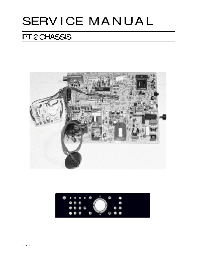
Image preview - the first page of the document
>> Download profilo_pt2_chassis_tv_sm_only_147 documenatation <<
Text preview - extract from the document
SERVICE MANUAL
PT 2 CHASSIS
Modification reserved
PT-2 Chassis Service Manual
CONTENTS
PAGE
Technical Data . . . . . . . . . . . . . . . . . . . . . . . . . . . . . . . . . . . . . . . . .5
Standard and optimal features . . . . . . . . . . . . . . . . . . . . . . . . . . . .5
Recommendation for service repairs . . . . . . . . . . . . . . . . . . .6
Scart pin description . . . . . . . . . . . . . . . . . . . . . . . . . . . . . . . .7
Component description . . . . . . . . . . . . . . . . . . . . . . . . . . . . .8
Adjustment procedure . . . . . . . . . . . . . . . . . . . . . . . . . . . . . .9
Usage of the service submenu . . . . . . . . . . . . . . . . . . . . . . .10
Block diagrams (mono and stereo) . . . . . . . . . . . . . . . . . . .12
Fault tracing diagram-power supply . . . . . . . . . . . . . . . . . . .14
Trouble shooting guide for main PCB . . . . . . . . . . . . . . . . . .15
Descriptions of the parts . . . . . . . . . . . . . . . . . . . . . . . . . . . .16
1- Switch mode power supply stage . . . . . . . . . . . . . . . . . . .16
2- Micro controller stage . . . . . . . . . . . . . . . . . . . . . . . . . . . . . .16
3- Analog operation part . . . . . . . . . . . . . . . . . . . . . . . . . . . . .16
4- Vertical deflection circuit . . . . . . . . . . . . . . . . . . . . . . . . . . .17
5- Horizontal drive circuit . . . . . . . . . . . . . . . . . . . . . . . . . . . . . .17
6- Sound output stage . . . . . . . . . . . . . . . . . . . . . . . . . . . . . . . .17
7- CRT stage . . . . . . . . . . . . . . . . . . . . . . . . . . . . . . . . . . . . . . .17
Descriptions of the integrated circuits . . . . . . . . . . . . . . . . .18
- TDA4605 (Power supply) . . . . . . . . . . . . . . . . . . . . . . . . . . . . .18
- SDA5250 (Micro controller - teletext) . . . . . . . . . . . . . . . . . . . .21
- 27C1001 (128Kx8 UV eprom) . . . . . . . . . . . . . . . . . . . . . . . . . .24
- 24C08 (8K (1x8) Eeprom) . . . . . . . . . . . . . . . . . . . . . . . . . . . . .25
- HEF 4053 (Triple 2-Channel anoloque multiplexer/demultiplexer 26
- TDA8361/TDA8362 (Anolog operation) . . . . . . . . . . . . . . . . . . .27
- TDA9821 (Dual channel - sound processor) . . . . . . . . . . . . . . .31
- TDA9830 (AM sound demodulator) . . . . . . . . . . . . . . . . . . . . .33
- TDA9840 (Stereo / dual sound processor) . . . . . . . . . . . . . . . . .34
- TDA9860 (Stereo sound processor) . . . . . . . . . . . . . . . . . . . . . .36
3
PT-2 Chassis Service Manual
- TBA120U (Fm demod and Af amp.) . . . . . . . . . . . . . . . . . . . .38
- TDA3845 (Fm Am sound) . . . . . . . . . . . . . . . . . . . . . . . . . . . .39
- TDA4470B (Multistandard video/sound IF signal processing) . . . 41
- TDA4665 (Baseband delay line) . . . . . . . . . . . . . . . . . . . . . . .45
- TDA8395 (Secam decoder) . . . . . . . . . . . . . . . . . . . . . . . . . .46
- SAA7283 (Terre strial digital sound decoder) . . . . . . . . . . . . . .47
- TDA7056A (Audio amp. for mono sets) . . . . . . . . . . . . . . . . . .52
- TDA7057AQ (`Audio amp. for stereo sets) . . . . . . . . . . . . . . . .53
- TDA3653B (Vertical deflection output) . . . . . . . . . . . . . . . . . .54
- TDA6103Q (Video output amplifier) . . . . . . . . . . . . . . . . . . . .55
- BUH515D (High voltage NPN fastswitvhing transistor) . . . . . . . .56
- BUZ90 (Power field effect transistor . . . . . . . . . . . . . . . . . . . . .59
RC hand unit and circuit diagram . . . . . . . . . . . . . . . . . . . .61
RC Transmitter PCB circuit diagram . . . . . . . . . . . . . . . . . . .62
Oscilloscope shapes . . . . . . . . . . . . . . . . . . . . . . . . . . . . . . .63
OPTIONAL BOARDS
- Nicam board circuit diagram . . . . . . . . . . . . . . . . . .64
- German stereo board circuit diagram . . . . . . . . . . .66
- Nicam L board circuit diagram . . . . . . . . . . . . . . . . .68
- A2 + Nicam L board circuit diagram . . . . . . . . . . . . .70
- Double scart board circuit diagram . . . . . . . . . . . . .72
- Main board circuit diagram . . . . . . . . . . . . . . . . . . . .74
Exploded wiews . . . . . . . . . . . . . . . . . . . . . . . . . . . . . . . . . . .76
Chassis replacement . . . . . . . . . . . . . . . . . . . . . . . . . . . . . . .78
The part list . . . . . . . . . . . . . . . . . . . . . . . . . . . . . . . . . . . . . . .79
4
PT-2 Chassis Service Manual
TECHNICAL DATA
STANDARD FEATURES
Tube 900 Max. 14", 20", 21" 4/3 CPT
Color System PAL B/G
Tuning System Voltage Synthesis Tuner
Power Source AC 165 V ~ 265 V
Power Consumption 60 W mono, 70 W Stereo
In Stand-By Mode Less Than 5 Watts
Channel Coverage VHF (2-4/5-12), UHF (21-69), CATV (S1-S41)
Number of Programs 99+1 AV (2 AV optional)
Audio Output 2x8 ohm stereo
2x8 ohm mono
Antenna Input 75 ohm IEC
STANDARD FEATURES OPTIONAL FEATURES
m ATS m Headphone
m Parental Lock m PAL I, PAL SECAM BG, PAL/SECAM
m Cable TV (Hyper Band) BG+DK
m Fine Tuning PAL/SECAM BG+LL', NTSC 4.43
playback
m Simple Text / Fast Text / Top Text
m German Stereo
m Auto Shut Off
m Normalization m Nicam BG, Nicam L, Nicam I
m German Stereo + Nicam L
m OSD with user friendly menu
m Sleep Timer m Double Scart
m Bass, Treble, Balance and Sound
m Real Time Clock From Teletext
Effect
Sync
m German Stereo + NICAM BG/I
m Hotel Mode
m Storing Program name with 4
character
m Top Ten List
m Menu Commands in 9 Language
m Euro AV
5
PT-2 Chassis Service Manual
RECOMMENDATION FOR SERVICE REPAIRS
1- Use only original spare parts. Only use compo- outside the cabinet or with back cover removed
nents with the same specifications for replace- involve a shock hazard from the receiver.
ment. Servicing should not be attempted by anyone
2- Original fuse value only should be used. who is not thoroughly familiar with the precauti-
3- Main leads and connecting leads should be ons necessary when working on high voltage
checked for external damage before connecti- equipment.
on. Perfectly discharge the high potential of the pic-
Check the insulation. ture tube before handling the tube. The picture
4- Parts contributing to the safety of the product tube is highly evacuated and if broken.
must not be damaged or obviously unsuitable. Glass fragments will be violently expelled.
This is valid especially for insulators and insulating Always discharge the picture tube anode to the
parts. receiver chassis to keep of the shock hazard be-
5- Thermally loaded solder pads are to be sucked fore removing the anode cap.
off and re-soldered. 8- Keep wire away from the high voltage or high
6- Ensure that the ventilation slots are not obstruc- temperature components.
ted. 9- When replacing a wattage resistor in circuit bo-
7- Potentials as high as 25 KV are present when this ard, keep the resistor 10 mm away from circuit
receiver is operating. Operation of the receiver board.
HANDLING OF MOS
CHIP COMPONENTS
MOS circuit requires special attention with regard until they are used. Most components must never
to static charges. Static charges may occur with be stored in styropor materials or plastic magazi-
any highly insulating plastics and can be transfer- nes.
red to persons wearing clothes and shoes made of 2- Persons have to rid themselves of electrostatic
synthetic materials. Protective circuits on the inputs charges by touching MOS components.
and outputs of mos circuits give protection to a li-
3- Hold the component by the body touching the
mited extend only due to time of reaction.
terminals.
Please observe the following instructions to protect 4- Use only grounded instruments for testing and
the components against damage from static char- processing purposes.
ges. 5- Remove or connect MOS ICs when operating
1- Keep mos components in conductive package voltage is disconnected.
X-RAY RADIATION
PRECAUTION
1- Excessive high voltage can be produce potenti- the reading of the high voltage be recorded as
ally hazardous X-RAY radiation. To avoid such ha- a part of the service record. It is important to use
zard, the high voltage must not be above the an accurate and reliable high voltage meter.
specified limit. The nominal value of the high vol- 2- The primary source of X-RAY radiation in this TV
tage of this receiver is 25KV at zero beam current receiver is the picture tube. For continued X-RAY
(minimum brightness) under 220V AC power sour- radiation protection, the replacement tube must
ce. The high voltage must not under any cir- be exactly the same type tube as specified in
cumstance, exceed 30KV. It is recommended the part list.
6
PT-2 Chassis Service Manual
SPECIFICATIONS OF THE CONNECTOR
(EURO SCART)
I- Audio output 1. right channel 0.5 VRMS/<1k
2- Audio input 1. right channel 0.5 VRMS (connected to No.6 on mono TV set.)
3- Audio output 2. left channel 0.5 VRMS (connected toNo.1 on mono TV set.)
4- GND (audio)
5- GND
6- Audio input 2. left channel 0.5 VRMS/>10k
7- RGB input, blue (B)
8- AV status
9- GND
10- Reserved for clock signals (not connected)
11- RGB input, green (G)
12- Reserved for remote control (not connected)
13- GND
14- GND switch signal RGB
15- RGB input, red (R)
16- RGB Switching input (1V dc)
17- GND (video)
18- GND19- Video output 1 Vpp/75 ohm
20- Video input 1 Vpp/75 ohm
21- Shield
1 3 5 7 9 11 13 15 17 19 21
2 4 6 8 10 12 14 16 18 20
7
PT-2 Chassis Service Manual
COMPONENT DESCRIPTIONS
POWER CORD
SAW FILTER
IR SENSOR
VOLTAGE REGULATOR
ON/OFF SWITCH
LINE FILTER
PTC
NPN TRANSISTOR
PNP TRANSISTOR
CERAMIC FILTER
COIL
LINEARITY COIL
FUSIBLE RESISTOR
IW METAL OXIDE RESISTOR
1/2W METAL OXIDE RESISTOR
1/4 OR 1/6W CARBON FILM RESISTOR
CERAMIC CAPACITOR /POLYESTER CAPACITOR
ELECTROLITIC CAPACITOR
DIODE
ZENER DIODE
SWITCH JUMPER
NET (INPUT)
NET (OUTPUT)
TACT SWITCH
8
PT-2 Chassis Service Manual
ADJUSTMENT PROCEDURE
1- System Voltage (+B) Adjustment :
m Before switching on TV, all potentiometers should be adjusted at medium level. Then TV is
switched on;
m Adjust all of the analog parameters to minimum with RC
m Adjust P1 trimpot until find +115 V on the cathode of D2 diode
2- AFT Adjustment:
m Place a balloon coil (300 Ohm dc resistance ) parallel to L104
m Apply 80 dB uV 38.9 MHz (39.5 MHz for I ) signal via balloon coil
m Connect a voltmeter to aft pin (pin 9) of IC301
m Adjust T101 coil until the voltage of this pin being 2.5 V dc
3- Adjustment of G2:
m Apply Philips Test pattern
m Adjust all of the analog parameters to minimum with RC
m Adjust G2 trimpot until seeing two bars on gray scale
4- Horizontal and Vertical Adjustment:
m Apply Philips Test pattern signal
m Center the picture horizontally while picture shifting to right and left with P101,
m Make vertical amplitude adjustment with P602 until seeing top and lower lines of picture will
be seen
m Center the picture with P601
5- AGC Adjustment:
m Apply Philips Test Pattern whose amplitude is 60 dB uV to the rf input
m Adjust P102 until find a picture without snowy
6- Focus Adjustment:
m Apply Cross-Hatch Pattern signal
m Find the optimum concentration point between H and V intersection in the middle of screen.
7- White Balance Adjustment :
m Apply Philips Test Pattern signal
m Adjust all of the trimpots on CRT board to medium level
m Adjust color, contrast, brightness to minimum by RC
m Adjust G2
m Apply white pattern, settle in the probe of color analyzer to screen
m Increase brightness until geting Y=10 nits
m Adjust x=270 - 276 nits y=270 - 276 nits via "VR201, VR203, VR205"
m Increase brightness and contrast until Y=90 - 100 nits
m Adjust x, y to same values via "VR202 and VR204"
m Check white balance at high and low contrast level. Again make adjustment if it's necessary.
9
PT-2 Chassis Service Manual
USAGE OF THE SERVICE SUBMENU
SOME TRICKS FOR THE SOFTWARE
If the customer does not remember the password for child lock you can solve this problem as the
following:
Step 1: Turn TV ON,
2: Push P+
3: Push P-
4: Push V+
5: Push V-
6: Push OK
keys respectively. Now, the lock was opened.
When you entered SERVICE line, the TV will ask a password to you:
The password is "089"
PARENTAL LOCK
TV-PROGRAMME CHART
AUTOMATIC PROGRAMMING
AUDIO/VIDEO INPUTS
SPECIAL FUNCTIONS
SERVICE
Ok Call up TV TV Picture
SERVICE
FOR AUTHORIZED DEALER ---
0-9 CODE TV TV-PICTURE
Enter "089" code for password
After entered "089" code, you will meet a menu as the following:
For authorized dealer
Factory set values
Production mode
Hotel mode off
Max. volume
Ok Call up TV TV Picture
10
PT-2 Chassis Service Manual
Factory set values:
If you press OK key on the first line (Factory set values), then the EEPROM is being cleared and stored so-
me original parameters.
All stored programs will be cleared.
Production mode:
You will see the following menu:
Production mode
Contrast
1 White level
2 Black level
3 Fast programming
P+, P- Change prog. number
M Return
You can adjust white and black level pressing 1 and 2 keys respectively. If you switch off the TV in this sub
menu, during the next opening, the TV starts to run from this menu directly. You should leave from this sub
menu pressing M key.
Fast programming is used in the factory.
Hotel Mode:
If you press V+/- key on this line, you can make the hotel mode as on. Now, you can adjust the maximum
available volume for hotel room. You leave from this sub menu pressing TV button.
If the Hotel Mode is ON, you can not use the
PARENTAL LOCK
TV-PROGRAMME CHART,
AUTOMATIC PROGRAMMING sub menus.
11
PT-2 Chassis Service Manual
12
PT-2 Chassis Service Manual
13
PT-2 Chassis Service Manual
FAULT TRACING DIAGRAM-POWER SUPPLY
Inportant Service Note :
Switched mode power
supply defective,+115 voltoge Before changing a component in the
is missing or level is wrong
Primary Mains Stage it is imperative,
that C5 is discharged by a resistor
of approx. 100 K.
D1,D2,D3,D4 YES Fuse eg.
C1,C2,C5 F01 defective
NO
ATTENTION!A short circuit transistor
NO Q602 can be a result of a defective
R1,Q1 Voltage at drain
D20, R20, or the cut-off
short circuit Q1 components
D5,R3
YES
Voltage at
YES
R5 IC630-(3)
< 1V
NO
R2,I2 YES Start-up voltage
IC630-(6)
D8 < 8V
NO
YES
Start-up voltage
Q 602
varies ca. 8V
NO
I1
Measure +115 V supply
NO +115V
P1,R9,ZD1 adjustable with
P1
YES
Control range of
switched-mode power
supply 165-270V
14
PT-2 Chassis Service Manual
TROUBLE SHOOTING GUIDE FOR MAIN PCB
TROUBLE CHECK POINTS
No color I 101, X 102, C 127, I 102, I101 pin 38
No vertical deflection Check +K, I 601, I101 pin 42, I 101 pin 43
Vertical linearity C 625, R 623
Vertical size C 626, R 624
Vertical shift R 626, P 601
Horizontal linearity L 601, C 608
Horizontal size +B, C 607, L 602
Flue picture I 101 pin 25, ABL, FOCUS, HEATER, EHT
Dark picture I 101 pin 17, SCREEN, EHT, +M
Noise picture TU 01, AGC, IF, F 101
Vert./horizontal synchrony X 102
Interference TU 01, IF, F 101
No sound Check I 101 pin 5 and pin 50, I 401 pin 3, pin 5, +G
Low sound I 101 pin 5, pin 50, I 401 pin 5, +G, R 403
Sound distortion I 401, +G, R 403
Contrast I 301 pin 81, I 101 pin 25, ABL
Brightness I 301 pin 82, I 101 pin 17
Color saturation I 301 pin 83, I 101 pin 26
Tuning I 301 pin 77, Q 301, +D,TU 01
Memory I 302, SDA, SCL
Band select I 301 pin 72, 74, 75, +K, TU 01, Q 302, 303, 304
No video-out on the SCART Check TV-VID signals, Q 651
No video-in on the SCART Check I 301 pin 76, I 101 pin 16 on AV mode, check the
video signals on AV mode SCART pin 20 and I 101 pin 101
No sound out on the SCART I 101 pin 1, Q 653 , Q654
No sound in on the SCART Check the audio signals on SCART pin 2/6 and I 101 pin 15
No remote control reception Check signals on pin 3, IR 01 and I 301 pin 73
15
PT-2 Chassis Service Manual
DESCRIPTION OF THE PARTS
1- SWITCH MODE POWER SUPPLY STAGE ed to be added a base-band delay line
(TDA4665) a tuner and output stages for au-
In order to supply the DC voltage required at
dio, video and horizontal and vertical def-
various parts of the chassis, an SMPS transfor-
lection. TDA8362 can handle signals with po-
mer controlled by the IC TDA 4605 and switc-
sitive modulation and it supplies the signals
hing transistor 3N90 (BUZ90) in used. CI, T1, C2
which are required for secam decoder
filter circuit prevents the network noises and
TDA8395.
the effects of high frequency which produced
in TV set. After rectifying DC voltage is filtered VIDEO AMPLIFIER The IF amplifier contains 3 AC-
by using C5. The start up voltage of TDA4605. coupled control stages with a total gain
This square wave reaches QI passing through control range of greater than 60 dB. The re-
R8. After that Q1 form and induction on T2, ference carrier for the video demodulator is
which produces a voltage on pin 6. This volta- obtained by means of passive regeneration
ge rectified by D6 is used as a supply voltage of the picture carrier. The external reference
of IC 1. IC 1 does not operates SMPS by stop- tuned circuit is the only remaining adjust-
ping pulses at pin 5, when the network is higher ment of the IC. In the TDA8362 the polarity of
or lover than fixed limits. Pin 2 is control pin of the demodulator can be switched so that
overload. This stage produces 115V for FBT, 12 the circuit is suitable for both positive and
V for audio part, 33 V for tuning circuit 5V, for negative modulated signals. The AFC circuit
tuner and some ICs and 8V (for TDA8362) are is driven with the same reference signal as
produce by the means of the regulators the video demodulator. To ensure that the
LM7805, LM317. This circuit operates between video content does not disturb the AFC ope-
165 VAC and 265 Vac (50Hz).(In stereo TV set ration a sample and hold circuit incorpora-
aditionally 7808) ted; the capacitor for this function is internal.
The AFC output voltages 6V. The AGC de-
tector operates on levels, top sync for nega-
2- MICRO CONTROLLER STAGE tive modulated and top white for positive
Below items are controlled or generated by modulated signal. The AGC detector time
means of this controllers. constant capacitor is connected externally.
m SDA 5250 are used as a controller and teletext SOUND IF CIRCUIT
decoder on PT2 chassis. On mono models
m Voltage synthesis tuning. The sound band pass and trap filters have to
m On screen display be connected externally. The filtered inter
m Control of two transmission standard. carrier signal is fed to a limetter circuit and is
demodulated by means of PLL demodula-
m Controls of the simple text or fast text decoder. tor. Type PLL circuit tunes it self automatically
m Full peri-TV (scart) switching on stereo models. to the incoming signal, consequently, no ad-
m Controls of stereo decoder TDA9840 and justment is required.
TDA9821 as German Stereo Decoder. The volume is DC controlled. The composite
m SAA7283 as Nicam decoder. audio output signal has an amplitude of 700
m Sound processing (Bass, treble, balance). mV RMS at a volume control setting of-6 dB.
The emphasis capacitor has to be connec-
m Controls of the analog values of the picture ted externally. The non-controlled audio sig-
(Brightness, Color, Contrast) nal can be obtained from pin 1 via a buffer
m SDA5250 hasn't got internal ROM, so 27C010 EP- stage. The amplitude of this signal is 350 mV
ROM is used for external ROM. RMS.
The TDA8362 external audio input signal must
3- ANALOG OPERATION PART WITH have an amplitude of 350mV RMS. The au-
TDA8362 dio/video switch is controlled via the chromi-
TDA8362 is a single-chip TV processor which nance input pin.
contains nearly all small signal functions that On stereo models
are required for color television receiver. For On stereo models, the adjustable sound out-
a complete receiver the following circuit ne- put pin (pin50) is used for mono sound. An
16
PT-2 Chassis Service Manual
external sound IF circuit TDA3845 is used for NI- during normal operation.
CAM B/G, I stereo systems. For NICAM L stereo
system, TDA4470B sound IF IC is used so that ob- 5- HORIZONTAL DRIVE CIRCUIT
tain AM sound and NICAM I sound carrier. On The horizontal drive pulses obtained from pin 37
German stereo system, TBA120U is used as FM of the 8362 are connected to base of
demodulator for second sound carrier. Q601(2SC1573) via R602. Q601 drives Q602
SYNCHRONIZATION CIRCUIT (BUH515D) via the drive transformer T602. T601 is
The sync is preceded by a voltage controlled the EHT transformer. +B (115V) is switched by
amplifier which adjust the sync pulse amplitude Q602 and T601 generates both "EHT, FOCUS,
to a fix level. G2 voltages required for CPT "and" 170V, he-
The sync pulses are then fed to the slicing stage ated voltage and 26V vertical supply voltage".
(separator) which operates at 50% of the ampli- The anode beam current information from pin 7
tude. The separated sync pulses are fed to the of T601 is used for reducing contrast at too high
first phase detector and to the coincidence beam currents, in order to stabilize the voltages
detector. The coincidence detector is used for derived from power supply.
transmitter identification and to detect whet-
her the line oscillator is synchronized. When the 6- SOUND OUTPUT STAGE
circuit is not synchronized, the voltage on the On mono models, TDA7056A is used as sound
peaking control pin (pin 14) is LOW so that this output amplifier with DC volume control. Pin 50
condition can be detected externally. of the TDA8362 is AC coupled to the input pin 3
The IC TDA8362 contains a start up circuit for of the TDA7056A via a RC filter. It is supplied by
the horizontal oscillator. When this feature is re- + 12V coming from a separate winding in the
quired a current of 6.5 mA has to be supplied to SMPS transformer. On stereo models, TDA705-
pin 36. 7AQ is used as sound amplifier. The sound level
COLOR DECODING is controlled by sound processor TDA9860 via
12C bus on stereo boards. The outputs of
TDA8362 contains PAL, SECAM and NTSC deco- TDA9860 (pin 15 and pin 18) is connected to
der (TDA8361 contains only PAL decoder) but it TDA7057AQ via a divider circuit and two capa-
can cooperate with the Secam add-on Secam citors.
decoder TDA8395. The communication betwe-
en two IC's is achieved via pin 32. The TDA8362
supplies the reference signal (4.43 MHz) for the 7- CRT STAGE
calibration system of the TDA8395 identification The TDA6103Q is used on CRT stage as video
of the color standard is via the same connecti- output amplifier. The TDA6103Q consist of Three
on. When a SECAM signal is detected by the monolithic video output amplifiers. Each ampli-
TDA8395 the IC will draw a current of 150◦ Jabse Service Manual Search 2026 ◦ Jabse Pravopis ◦ onTap.bg ◦ Other service manual resources online : Fixya ◦ eServiceinfo