Service Manuals, User Guides, Schematic Diagrams or docs for : . Rare and Ancient Equipment PROFILO TV profilo_sm1_mono_chassis_tv_sm_only_888
<< Back | HomeMost service manuals and schematics are PDF files, so You will need Adobre Acrobat Reader to view : Acrobat Download Some of the files are DjVu format. Readers and resources available here : DjVu Resources
For the compressed files, most common are zip and rar. Please, extract files with Your favorite compression software ( WinZip, WinRAR ... ) before viewing. If a document has multiple parts, You should download all, before extracting.
Good luck. Repair on Your own risk. Make sure You know what You are doing.
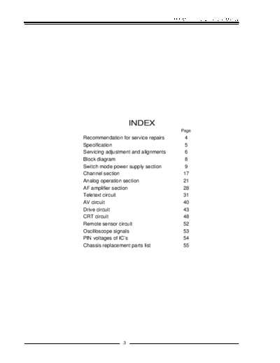
Image preview - the first page of the document
>> Download profilo_sm1_mono_chassis_tv_sm_only_888 documenatation <<
Text preview - extract from the document
                                      SM 1 Mono Chassis Service Manual


                     INDEX
                                          Page
Recommendation for service repairs         4
Specification                              5
Servicing adjustment and alignments        6
Block diagram                              8
Switch mode power supply section           9
Channel section                            17
Analog operation section                   21
AF amplifier section                       28
Teletext circuit                           31
AV circuit                                 40
Drive circuit                              43
CRT circuit                                48
Remote sensor circuit                      52
Oscilloscope signals                       53
PIN voltages of IC's                       54
Chassis replacement parts list             55


                 3
SM 1 Mono Chassis Service Manual


RECOMMENDATION FOR SERVICE REPAIRS
     1- Use only original spare parts. Only use components with the same specifications for replacement.
     2- Original fuse value only should be used.
     3- Main leads and connecting leads should be checked for external damage before connection. Check
     the insulation.
     4- Parts contributing to the safety of the product must not be damaged or obviously unsuitable.
     This is valid especially for insulators and insulating parts.
     5- Thermally loaded solder pads are to be sucked off and re-soldered.
     6- Ensure that the ventilation slots are not obstructed.
     7- Potentials as high as 25 KV are present when this receiver is operating. Operation of the receiver
     outside the cabinet or with back cover removed involve a shock hazard from the receiver.
     Servicing should not be attempted by anyone who is not thoroughly familiar with the precautions
     necessary when working on high voltage equipment. Perfectly discharge the high potential of the pic-
     ture tube before handling the tube. The picture tube is highly evacuated and if broken. Glass frogments
     will be violently expelled.
     Always discharge the picture tube anode to the receiver chassis to keep of the shock hazard before re-
     moving the anode cap.
     8- Keep wire away from the high voltage or high temperature components.
     9- When replacing a wattage resistor in circuit board, keep the resistor 10 mm away from circuit board.

HANDLING OF MOS CHIP COMPONENTS
     MOS circuit requires special attention with regard to static charges. Static charges may occur with any
     highly insulating plastics and can be transferred to persons wearing clothes and shoes made of synthe-
     tic materials. Protective circuits on the inputs and outputs of mos circuits give protection to a limited ex-
     tend only due to time of reaction.
     Please observe the following instructions to protect the components against damage from static char-
     ges.
     1- Keep MOS components in conductive package until they are used. Most components must never be
     stored in styropor materials or plastic magazines.
     2- Persons have to rid themselves of electrostatic charges by touching MOS components.
     3- Hold the component by the body touching the terminals.
     4- Use only grounded instruments for testing and processing purposes.
     5- Remove or connect mos ics when operating voltage is disconnected.

X-RAY RADIATION PRECAUTION
     1- Excessive high voltage can be produce potentially hazardous X-RAY radiation. To avoid such ha-
     zard,
     the high voltage must not be above the specified limit. The nominal value of the high voltage of this re-
     ceiver is 25KV at zero beam current (minimum brightness) under 220V AC power source. The high
     voltage must not under any circumstance, exceed 30KV. It is recommended the reading of the high
     voltage be recorded as a part of the service record. It is important to use an accurate and reliable high
     voltage meter.
     2- The primary source of X-RAY radiation in this TV receiver is the picture tube. For continued X-RAY
     radiation protection, the replacement tube must be exactly the same type tube as specified in the part
     list.


                                                       4
                                                                           SM 1 Mono Chassis Service Manual


SPECIFICATION

   POWER SUPPLIES
   Nominal: 220V AC 50 Hz. The chassis is fully mains isolated and is stabilized across mains voltage range from
   165V to 265V for less than 0.75 % change in picture size. No mains input adjustment is required.

   POWER CONSUMPTION
   Typically: 75 W, Maximum: 95 W (for 20" and 21" models)

   FREQUENCY COVERAGE
   Hyperband (VHF CH 2 to UHF CH 69 including CATV): 47-862 MHz
   UHF (CH 21-69): 471-862 MHz

   IF FREQUENCIES (in MHz)

                      VISION     SOUND
   B/G (EUROPE)     :    38.9 33.4
   I (UK)  :   39.5 33.5
   L' (FRANCE) :    32.7 39.2
   L (FRANCE) :     39.2 32.7
   D/K (USSR) :     38.0 31.5


                                                 5
SM 1 Mono Chassis Service Manual


SERVICING ADJUSTMENTS AND ALIGNMENTS
         l                   HIGH VOLTAGE TEST
     There is no high voltage adjustment component on the chassis. Changing of +120 depends on the supply
     voltage. If high voltage is to measured.
     1- Connect the + probe of high voltage tester to the anode of cpt.
     2- Adjust contrast and brightness to minimum.
     3- Measure the high voltage as 23.0+5%KVdc for 14". That voltage is 25. 5
◦ Jabse Service Manual Search 2026 ◦ Jabse Pravopis ◦ onTap.bg ◦ Other service manual resources online : Fixya ◦ eServiceinfo