Service Manuals, User Guides, Schematic Diagrams or docs for : . Rare and Ancient Equipment Prolodgy car audio Prology CMD-170s
<< Back | HomeMost service manuals and schematics are PDF files, so You will need Adobre Acrobat Reader to view : Acrobat Download Some of the files are DjVu format. Readers and resources available here : DjVu Resources
For the compressed files, most common are zip and rar. Please, extract files with Your favorite compression software ( WinZip, WinRAR ... ) before viewing. If a document has multiple parts, You should download all, before extracting.
Good luck. Repair on Your own risk. Make sure You know what You are doing.
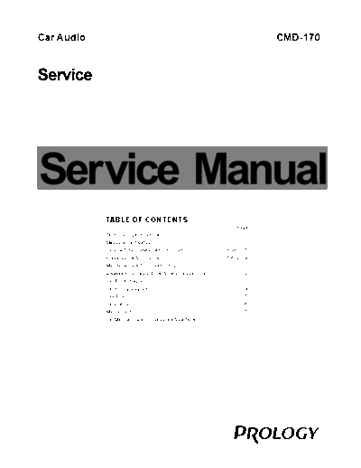
Image preview - the first page of the document

>> Download Prology CMD-170s documenatation <<
Text preview - extract from the document
Car Audio                                                                                                   CMD-170


            TABLE OF CONTENTS
                                                                                                 Page
            Technical Specificatio ns ............. .................. .................. ...1-2
            Measurem ent setup . .................. .................. .. ...... .......... ...1-3
            Service A ids, Safety I nstruction, et c ....... ...... .. ........... 1-4 to 1-5
            Preparati ons & Contro ls .............. ......... ...... ... ........... 1-6 to 1-9
            Maintena nce & Troubl eshooting ....................... ................ 1-10
            Disassem bly Instructi ons & Servic e positions . .... ...... ........ ..... 2
            Set Block diagram .... .................. ................ .. .... .............. ..... 3
            Set Wirin g diagram ... .................. ....... ...... ..... .................. ..... 4
            Key Board ................ .......................... ................................. 5
            Servo Board ............. ........................... ...... .......................... 6
            Main Boa rd .............. .................. ......... ...... ... .................. ..... 7
            Set Mech anical Explo ded view & p arts list .... .. .... .............. ...... 8
                                                                        1-2
SPECIFICATIONS

     General                                                                       Components
Power supply:                   12V DC(11V-16V)                                Mounting collar             1
                                Test voltage 14.4V, negative ground            Machine screws M5x6mm       4
Maximum power output:           50Wx4 channels                                 Mounting bolt (50mm)        1
Continuous power output:        25Wx4 channels (4 ,10% T.H.D.)                 Wire connector              1
Suitable speaker impedance:     4-8 ohm                                        Removable face plate case   1
Pre-Amp output voltage:         2.0V ( CD play mode: 1KHz, 0 dB, 10 K load )   Trim plate                  1
Fuse:                           15A                                            L-key                       2
Dimensions(WxHxD)               178x50x162mm                                   Operating instructions      1
Weight:                         1.7kg                                          Rubber cushion              1


     FM Stereo Radio
Frequency range:                     87.5 - 108.0 MHz ( EUROPE mode )
                                     65.0 - 74.0 MHz ( OIRT mode )
Usable sensitivity:                  8 dB
quieting sensitivity(S/N=50dB):      12 dB
Frequency response:                  30Hz-15kHz
Stereo separation:                   30dB(1kHz)
Image response ratio:                50dB
IF response ratio:                   70dB
Signal/noise ratio                   55dB


    Disc Player
System:                           Disc digital audio system
Frequency response:               20Hz - 20kHz
Signal/noise ratio:               >86 dB
Total harmonic distor tion:       Less than 0.20%(1 kHz)
Wow and flutter:                  Below measurable limits
Channel separation:               >60 dB


Note: Specifications and design are subject to change
      without notice for product improvements.
                                                                                                1-6
PREPARATIONS

   Wiring Diagram


                Antenna                                                                                            Fuse 15A


                                                                                                       Connector
                                                                                                                                                               A mplifier
                                                                                                        Line-out (Gray)                      R(Red)
                                                                                                                                             L(White)


                                                  ISO Connector                                                      For some VW /Audi or Opel(Vaux hall)
                                                                                                                     car models, you may need to modify
                                                                                                                     w iring of the supplied power cord as
                                       Yellow                                                                        illustrated, or else th e memory of the
                                                          To car battery(+) Continuous +12V DC
                                                                                                                     uni t may be lost after you power off.
                                       Black
                                                          Ground Lead                                                Cont act your authori zed car dea ler
                                       Blue               Motor/Electric Antenna relay control Lead                  before i nsta lling this unit .
                                                          Amplifier relay control Lead
                                       Red                                                                              Ori ginal wi ring
                                                          Ignition key                                                          Yellow         Yellow
                                                           +12V DC When ON/ACC
                                                                                                                                Red            Red
 Purple Purple/ Gray Gray/    White/ White Green/ Green
        Black        Black    Black        Black
        Stripe       Stripe   Stripe       Stripe                                                                         Modified wir ing
                                                                                                                                Yellow         Yellow

                                                                                                                                Red            Red


       Using the ISO Connector
       1.If your car is equipped with the ISO connector, then connect the ISO connectors as illustrated.


       2. For connections without the ISO connectors, check the wiring in the vehicle carefully before connecting,
          incorrect connection may cause serious damage to this unit.
          Cut the connector, connect the colored leads of the power cord to the car battery, as shown in the colour
          code table below for speaker and power cable connections


                                       Connector                                     Connector
                                                                                Rear Right(+)---Purple
                                                                          Rear Right(-)---Purple/Black Stripe
                                                                                 Front Right(+)---Gray
                                         ACC+/red                         Front Right(-)---Gray/Black Stripe
                                     Auto Antenna/blue                           Front Left(+)---White
                                                                           Front Left((-)---White/Black Stripe
                                  Battery 12V (+)/yellow                          Rear Left(+)---Green
                                        Ground/black                        Rear Left(-)---Green/Black Stripe
                          5-2   5-2

KEY BOARD - CIRCUIT DIAGRAM
                         6-2    6-2

SERVO BOARD - CIRCUIT DIAGRAM
                               7-2   7-2

MAIN BOARD - CIRCUIT DIAGRAM
◦ Jabse Service Manual Search 2024 ◦ Jabse Pravopis ◦ onTap.bg ◦ Other service manual resources online : Fixya ◦ eServiceinfo