Service Manuals, User Guides, Schematic Diagrams or docs for : . Rare and Ancient Equipment Prolodgy car audio Prology CMD-220s
<< Back | HomeMost service manuals and schematics are PDF files, so You will need Adobre Acrobat Reader to view : Acrobat Download Some of the files are DjVu format. Readers and resources available here : DjVu Resources
For the compressed files, most common are zip and rar. Please, extract files with Your favorite compression software ( WinZip, WinRAR ... ) before viewing. If a document has multiple parts, You should download all, before extracting.
Good luck. Repair on Your own risk. Make sure You know what You are doing.
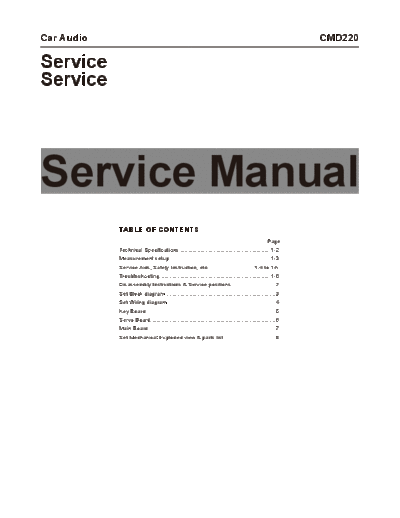
Image preview - the first page of the document

>> Download Prology CMD-220s documenatation <<
Text preview - extract from the document
Car Audio                                                                                                    CMD220

Service
Service


Service Manual
            TABLE OF CONTENTS
                                                                                                   Page
            Technical Specifications.......................................................... 1-2
            Measurement setup. ............................................................... 1-3
                             .
            Service Aids, Safety Instruction, etc.............................. 1-4 to 1-5
            Troubleshooting....................................................................... 1-6
            Disassembly Instructions & Service positions ............................2
            Set Block diagram.......................................................................3
            Set Wiring diagram......................................................................4
            Key Board. ..................................................................................5
                     .
            Servo Board................................................................................6
            Main Board..................................................................................7
            Set Mechanical Exploded view & parts list..................................8
                                                                     1-2
SPECIFICATIONS

General
Power supply                   12V DC(11V-16V)
                               Test voltage 14.4V, negative ground
Maximum power output           50Wx4 channels
Continuous power output        25Wx4 channels (4 10% T.H.D.)
Suitable speaker impedance     4-8 ohm
Pre-Amp output voltage         4.0V(CD play mode: 1KHz, 0 dB, 10 K load)
Fuse                           15A
ESP(optional)                  30s(CD-DA)/120s (MP3)
Weight                         2.38kg
Dimensions(WxHxD)              188x100x168mm
Aux-in                         300mv

FM Stereo Radio
Frequency range                87.5 - 108.0 Mhz (Europe mode)
                               87.5 - 107.9 Mhz (USA mode)
Usable sensitivity             8 dB
Frequency response             30 Hz-15kHz
Stereo separation              30dB(1 kHz)
Image response ratio           50dB
IF response ratio              70dB
Signal/noise ratio             55dB


AM(MW) Radio
Frequency range                522-1620 khz (Europe mode)
                               530-1710 khz (USA mode)
Usable sensitivity(S/N=20dB)   30 dB


Disc Player
System                         Disc digital audio system
Frequency response             20 Hz - 20 kHz
Signal/noise ratio             >86 dB
Total harmonic distortion      Less than 0.20%(1 kHz)
Wowandflutter                  Belowmeasurablelimits
Channel separation             >60 dB


Components
Mounting collar                1
Wire connector                 1
Operating instructions         1
Rubber cushion                 1


Note:Specificationsandthedesignaresubjecttochangewithoutnoticeduetoimprovementsintechnology.
                    1-3
MEASUREMENT SETUP
                           1-4
HANDLING CHIP COMPONENTS
1-5
                                                                            1-6
TROUBLESHOOTING

If you suspect something is wrong, immediately switch power off. Do not use the unit in abnormal condition, for example without sound, or with
smoke or foul smell, can cause fire or electric shock. Immediately stop using it and call the store where you purchased it. Never try to repair the
unit yourself because it is dangerous to do so.


General
                             Car's engine switch is not on:        Turn your car's key to ACC or ON.
    No power or              Cable is not correctly connected:     Check connection.
     no sound                Fuse is burnt. Replace fuse:          Check volume or mute on / off.
                             If the above solutions cannot help:   Press the RESET button.
Disc

 Disc is inside but          Disc is upside down:                  Place disc in the correct direction,and the label side up.
    no sound.                Disc is dirty or damaged:             Clean disc or change another disc.


 Disc sound skips,
                             Disc is dirty or damaged:             Clean CD or change another CD.
tone quality is low.


 Sound skips due             Mounting angle is over 30o:           Adjust mounting angle to less than 30o.
   to vibration.             Unstable mounting:                    Mount the unit securely with the mounting parts.

Radio

   Much noise in
                             Station is too far, or signals are too weak:         Select other stations of higher signal level.
    broadcasts


   Preset station
                             Battery cable is not correctly connected:            Connect the battery cable to the terminal that is always live.
       lost


Error Display Messages

                             Disc mechanism error: Press              button more than 2 seconds to eject the disc. In case that the disc
                             cannot be ejected by pressing           button, press the RESET switch and press the       button 2 seconds
                             to eject the disc. If still not ejecting, consult your dealer.


                             Disc upside down.


                             Disc format is not support or file date is wrong, check the disc.
                                         2-1                                                                 2-1

DISMANTLING INSTRUCTIONS

1. Remove the front panel.


                                                                   Pull out the
                                                                   FPC wire.


2. Remove the top, bottom cover and heatsank.


              Loosen the 2 pcs screw
              to remove the top cover.
                                                Loosen the 11 pcs screw
                                                to remove the heatsank.


            Loosen the 2 pcs screw
            to remove the bottom
            cover.


4. Loosen 4 pcs screw to remove the deck and mainboard.


                                                                                  Loosen the 2 pcs screw
                                                                                  to remove the mainboard.


                          Loosen the 2
                          pcs screw.


                                                  Pull out the 2
                                                  FPC wires.


       Loosen the 2 pcs screw.
                            2-2                             2-2

DISMANTLING INSTRUCTIONS


                           Service Position A   Service PositionC


                           Service Position B   Service Position D
                    3   3

SET BLOCK DIAGRAM
                     4   4

SET WIRING DIAGRAM
                             5-1                                                                      5-1

                                                                                LCD PIN CONNECTION


KEY BOARD


                                                                                PIN SEGMENT DISPLAY
TABLE OF CONTENTS

LCD Display . . . . . . . . . . . . . . . . . . . . . . . . . . . . . . . 5-1
Circuit Diagram . . . . . . . . . . . . . . . . . . . . . . . . . . . . 5-2
Layout Diagram . . . . . . . . . . . . . . . . . . . . . . . . . . . . 5-3
Electrical Parts List . . . . . . . . . . . . . . . . . . . . . . . . . 5-4
                          5-2   5-2

CIRCUIT DIAGRAM - KEY BOARD
                             5-3   5-3

LAYOUT DIAGRAM - KEY BOARD
TOP VIEW


LAYOUT DIAGRAM - KEY BOARD
BOTTOM VIEW
                                           5-4                                                           5-4

ELECTRICAL PARTS LIST - KEY BOARD

Part No.       Description                                         QTY   Location
121604000102   RES,1K? ,
◦ Jabse Service Manual Search 2024 ◦ Jabse Pravopis ◦ onTap.bg ◦ Other service manual resources online : Fixya ◦ eServiceinfo