Service Manuals, User Guides, Schematic Diagrams or docs for : . Rare and Ancient Equipment Rolsen VCR Сервисные мануалы RVC601 Deck
<< Back | HomeMost service manuals and schematics are PDF files, so You will need Adobre Acrobat Reader to view : Acrobat Download Some of the files are DjVu format. Readers and resources available here : DjVu Resources
For the compressed files, most common are zip and rar. Please, extract files with Your favorite compression software ( WinZip, WinRAR ... ) before viewing. If a document has multiple parts, You should download all, before extracting.
Good luck. Repair on Your own risk. Make sure You know what You are doing.
Image preview - the first page of the document
>> Download RVC601 Deck documenatation <<
Text preview - extract from the document
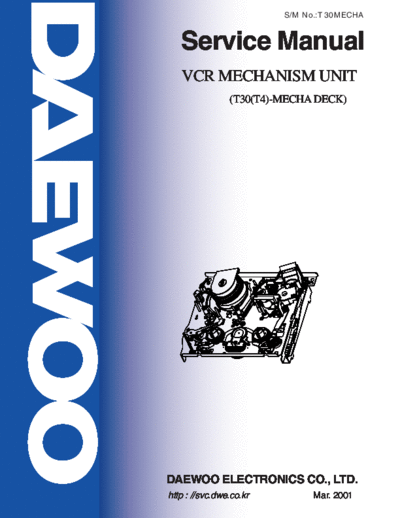
                         S/M No.:T 30MECHA


   Service Manual
   VCR MECHANISM UNIT
                (T30(T4)-MECHA DECK)


DAEWOO ELECTRONICS CO., LTD.
http : //svc.dwe.co.kr         Mar. 2001
 CONTENTS

1. ASSEMBLY DIAGRAM                       2
2. DISASSEMBLY DIAGRAM & REPLACEMENT      5
3. MECHANICAL ADJUSTMENT                  12
4. ADJUSTMENT OF TAPE TRANSPORT SECTION   14
5. EXPLODED VIEW                          19
6. PARTS LIST                             23


                     1
1. Assembly diagram
  1-1. DECK Assembly diagram
      A. Upper View


                                      Fig.1.1

1 MAINBASE ASS'Y               9 IDLER PLATE TOTAL ASS'Y    17 AC HEAD ASS'Y
2 DRUM ASS'Y                   10 T BRAKE ASS'Y             18 T SLANT POLE ASS'Y
3 FE HEAD                      11 FL RACK                   19 HEAD CLEANER
4 S SLANT POLE ASS'Y           12 RELAY LEVER
5 TENSION BAND ASS'Y           13 CAPSTAN MOTOR
6 S BRAKE ASS'Y                14 LC BRKT ASS'Y
7 S REEL TABLE                 15 PINCH LEVER TOTAL ASS'Y
8 REEL BRKT TOTAL ASS'Y        16 CAM GEAR


                                                2
      B. Bottom View


                       Fig.1.2

20 L LOADING ASS'Y
21 R LOADING ASS'Y
22 CONNECT PLATE
23 REEL BELT
24 LOADING RACK


                            3
  1-2. FRONT LOADING Assembly diagram


                                        Fig.2


1 FL BRKT L                                     5 CST HOLDER AS
2 TOP PLATE                                     6 DOOR OPENER
3 SAFETY LEVER                                  7 SAFETY LEVER R
4 LOADING LEVER AS4                             8 FL BRKT R


                                           4
2. DISASSEMBLY AND REPLACEMENT
2-1. Removal of the FRONT LOADING Ass'y                    2-2. Disassembly of FRONT LOADING Ass'y
     (Fig. 3.1)                                                 (FIg. 3.2~3.5)
 NOTE:                                                     a. Remove the washer holding the door opener and separate
                                                              F/L Assembly by moving the DOOR OPENER in the
 Remove the FRONT LOADING Ass'y in eject mode.                direction of arrow.
                                                           b. Remove the 2 screw holding the TOP PLATE and sepa-
a. Unscrew the 2 screw holding the F/L ass'y.                 rate the CASSETTE HOLDER Ass'y by moving the FL
b. Separate the F/L Ass'y from the MAINBASE ass'y by          BRKT L and FL BRKT R in the direction of arrow. (Fig.
   lifting the rear part of F/L (Screw Hole).                 3.2)


    Fig. 3.1 Removal of the FRONT LOADING Ass'y


                                                              FIg. 3.2 Disassembly of the FRONT LOADING Ass'y


                                                       5
c. Separate the LOADING LEVER Ass'y by pressing the                  2-3. Disassembly of DRUM Ass'y (Fig. 3.5)
   connection point from the CASSETTE HOLDER Ass'y.
   (Fig. 3.4)                                                        a. Turn over the DECK MECHANISM and holding the
                                                                        DRUM TOTAL Ass'y @ with hands, remove the 3
d. Remove the SAFETY SPRING connecting the SAFETY                       screw holding the drum total assembly with mainbase.
   LEVER and CASSTTE HOLDER PLATE. (Fig. 3.3)
                                                                     b. Separate the DRUM TOTAL Ass'y from the deck paying
e. Remove the RELEASE SPRING connecting the                             attention there is no damage on the surface of VIDEO
   RELEASE LEVER and SAFETY LEVER. (Fig. 3.3)                           HEAD and DRUM.
                                                                     c. Assemble in the reverse order of disassembly.

                                                                      CAUTION:
◦ Jabse Service Manual Search 2026 ◦ Jabse Pravopis ◦ onTap.bg ◦ Other service manual resources online : Fixya ◦ eServiceinfo