Service Manuals, User Guides, Schematic Diagrams or docs for : . Rare and Ancient Equipment Valhalla 2734A Valhalla_2734A_Direct_Voltage_Reference_Bank
<< Back | HomeMost service manuals and schematics are PDF files, so You will need Adobre Acrobat Reader to view : Acrobat Download Some of the files are DjVu format. Readers and resources available here : DjVu Resources
For the compressed files, most common are zip and rar. Please, extract files with Your favorite compression software ( WinZip, WinRAR ... ) before viewing. If a document has multiple parts, You should download all, before extracting.
Good luck. Repair on Your own risk. Make sure You know what You are doing.
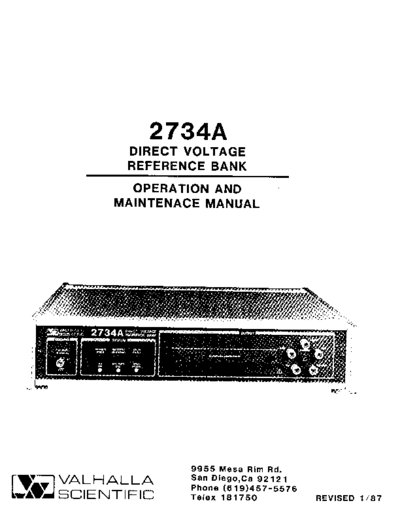
Image preview - the first page of the document
>> Download Valhalla_2734A_Direct_Voltage_Reference_Bank documenatation <<
Text preview - extract from the document
2734A
DIRECT VOLTAGE
REFERENCE BANK
OPERATION AND
MAINTENACE MANUAL
9955 Mesa Rim Rd.
VALHALLA
tlE SCIENTIFIC San Diego,Ca 92121
Phone (6 19)457 -SSZ6
Telex 181 75O REVTSED 1 / 87
CERTIFICATION
valhalla scientific, Inc. certif ies that this instrument lYas
thoroughly tested and inspected and found to meet it's
published specif ications when it was shipped f rom the factory.
valhalla scientif ic, Inc. further certifies that it's calibration
measurements are traceable to the National Bureau of Standards
to the extent allowed by NBS's calibration facility.
WARRANTY
The warranty period for this instrument is stated on your
invoice and packing list. Please refer to these to determine
appropriate warranty dates. We will repair or replace the
instrument during the warranty period provided it is returned
to valhalla Scientif ic, Inc. f reight prepaid. No other warranty
is expressed or implied. we are not liable for consequential
damages. Permission and a return authorization number must
be obtained directly from the factory for warranty repair
returns. No liability will be accepted if returned without such
permission.
TABLE OF CONTENTS
SECTION NUMBER PAGE
SECTION I- UNPACKING AND INSTALLATION t-l
SECTION II - SPECIFICATIONS 2-1
SECTION III - AVAILABLE OPTIONS 1l
SECTION IV - FRONT PANEL CONTROLS AND CONNECTIONS :1
t- I
|
SECTION V - REAR PANEL CONTROLS AND CONNECTORS 5- l
SECTION VI - MANUAL OPERATION o-l
SECTION VII - REMOTE OPERATION l-l
SECTION VII - CALIBRATION 8- r
SECTION IX - MAINTENANCE AND TROUBLESHOOTING 9-l
SECTION X - THEORY OF OPERATION r0- r
SECTION XI - PERFORMANCE VERIFICATION Il-l
SECTION XII - USEFUL HINTS t:- I
SECTION XIII - MANUAL CHANGE INFORMATION l3- r
SECTION XIV - SCHEMATIC AND ASSEMBLY DIAGRAMS t4- I
SECTION XV - PARTS LISTS r5- l
l-l
SECTION I. UNPACKING AND INSTALLATION
1.1 Unpacking
If the shipping carton is damaged, request that the carriers' agent be present when the
2734A is unpacked. If the 2734A appears damaged when unpacked, then notify the
carriers' agent who should authorize repairs before the 2734A is returned to Valhalla
Scientific or Service Center. Even if the 2734A appears undamaged, it may have suffered
internal damage in transit that may not be evident until the 2734A is operated or testecl
to verify performance. If the 2734A fails to meet the performance specifications in
Section II, then notify the carriers' agent and Valhalla Scientific or Service Center.
Retain the shipping carton for the carriers inspection. DO NOT RETURN EQUIPMENT
TO VALHALLA SCIENTIFIC OR ANY OF ITS SERVICE CENTERS PRIOR TO OBTAINING
AUTHORIZATION TO DO SO.
1.2 Initial Adjustments
The only adjustments required prior to operation of the 2734A are the correct selection
of the local power source voltage and to verify that the correct fuse for this voitaee is
fitted. The supply voltages and fuses are listed below:
105 to l28VAC 50/60H2 I Amp Slo Blo Fuse
210 to 256VAC 50/60H2 0.5 Amp Slo Blo Fuse
The user should note that both fuses are contained within the power socket on the rear
panel, and are automatically selected when the power line voltage selection is macle.
Either 20mm. or 1.25" fuse sizes may be used.
THE 2734A IS SHIPPED IN ''TRANSIT MODE'" POWERED BY INTERNAL BATTERIES. IT IS
RECON{NIENDED THAT THE UNIT HAVE POWER APPLIED AS SOON AS POSSIBLE AFTIII
UNPACKING IN ORDER TO MAINTAIN THE TRACEABILITY OF THE SPECIFICATION.
ENSURE THAT THE CORRECT SELECTION IS MADE PRIOR TO APPLYING POWER TO-|IIE
27 31A.
1.3 Instructions for Bench Use
The 2134A is delivered for operation in bench use and special instructions for use in this
manner are not required. However, before connecting the 2134A to the AC power
source, the user should verify that the power cord is equipped with a three-terminal
connector (see the Safety Precautions in 1.5).
1.'1 Instructions for Rack Mounting
Optional rack mounting brackets are available for mounting the 2734A in a standard l9'
an,rinment ranlq. These are listed in Section III of this manual. The size and weieht of
rrrqrruqr, r tru JIz!
the 2134A dictate that the unit should be supported on both sides along it's enrire length
(by the use of "trays" or "slides"). If it is to be transported while mounted in a rack
thEN it MUST BE SUPPORTED SO AS TO PREVENT UPWARDS AND DOWNWARDS
MOVEMENT.
l-t
The user should note that the specifications of the 2734A become degraded at high
temperatures. It is recommended that sufficient room be allowed for airflow around the
2734A. This may be achieved by placing at least l.75" high blank panels above and
below the 2734A in the rack.
If the unit is placed beneath the 2734A has an exceptionally hot exterior top surface,
and it is not possible to alter its location, the user is recommended to fit an aluminum
"reflector" plate between this unit and the 2'734A.
Under no circumstances should the ambient air temperature surrounding the 2718A be
allowed to exceed 50C while in operation or 70C while not in operation.
1.5 Safety Precautions
The power connector should be a three-contact device meeting the safety requirements of
the area in which the 2734A is to be used, and should only be mated with a three-
contact connector where the third contact provides ground connection. If power is
provided through an extension cable then the ground connection must be continuous
throughout this cable to the 2734A.
FAILURE TO PRO\/IDE A CONTINUOUS GROUND CONNECTION TO THE 2734A I\{AY RENDER
THE UNIT UNSAFE FOR USE.
t-2
SECTION II . SPECIFICATIONS
2.1 General
The specifications of the 2734A Direct Voltage Reference Bank are listed in the followine
paragraphs.
2.2 Stability
The stability figures given below are valid for ambient temperatures between l8 and 28C
and assume continuous application of power.
OUTPUT 30 days 90 days 180 days I year
l.0V l.Oppm 2.0ppm 3.0ppm 5.0ppm
l.0l 8V I .Oppm 2.0ppm 3.0ppm 5.0ppm
Y7 0.4ppm 0.8ppm l.6ppm 3.0ppm
lOV 0.5ppm l.3ppm 2.5ppm 4.0ppm
Each2734A is shipped "hot" (in transit mode) from Valhalla Scientific in San Diego, CA,
USA, the initial adjustments made by Valhalla Scientific acheives a worst case traceable
error against the US national volt of l.5ppm. This figure may be used with the
specifications above as a traceable uncertainty if the 2734A has AC power applied within
48 hours (144 hours if shipped in option TC34) of leaving Valhalla Scientific Inc and
following 2 hours stabilization. Each 2734A is shipped with the actual measured values
of each output quoted on a certificate with 0.lppm resolution.
2.3 Settability
Each of the 2734A outputs may be adjusted over the range and with the resolution shorvn
in the table below :
OUTPUT ADJUSTMENT RANGE RESOLUTION
l.OV l0ppm total 0.02ppm
l.0l8v lOppm total 0.02ppm
Y7 @ refs) 70ppm total 0.l4ppm
Y7 Q ref) 280ppm total 0.56ppm
lOV 5ppm total 0.0lppm
2.4 Temperature Coefficients
The temperature coefficients listed below are applicable within the 0 to 18C and 28 to
40C temperature ranges following l5 minutes of stabilization at the new ambient
conditions.
OUTPUT COEFFICIENT
l OV 0.Ippm/C
.018V
I 0.Ippm/C
Y7 0.02ppm/C
lOV 0.05ppm/C
z-l
2.5 Temperature Shock
Ambient temperature changes of greater than l0C per minute may cause a non-
accumulative change in output voltage of no greater than 0.0lppm/C change.
2.6 Output Drive and Resistance
The output resistance of each output at the respective terminal is as listed in the table
below :
OUTPUT MAX DRIVE RESISTANCE
l.OV 857.14 ohm +/- 0.0050/o
l.0l8v 869.95 ohm +/- 0.0050/o
Y7 3mA 0.05 ohm maximum
lOV l2mA 0.005 ohm maximum
Any (or all) of the outputs may be shorted indefinately, are protected against the
external application of transients up to 1200V peak, and may continuously source or sink
up to l00mA of current without permenant damage.
2.7 Supply Regulation
The maximum change in output voltage caused by a change in supply voltage from the
minimum to the maximum value/frequency specified is less than 0.05ppm following a l0
second delay. The maximum change in output voltage caused by a change in supply
source is less than 0.05ppm following a l0 second delay.
If a complete loss of power occurs then a non-accumulative change in output voltage of
less than 0.lppm may occur following stabilzation after re-application of power.
2.8 Output Noise
OUTPUT 0.01 to l0Hz BANDWIDTH l0Hz to 20KHz BANDWIDTHI
l.0V 0.luV peak maximum 3uV RMS maximum
l.0l8v 0.luV peak maximum 3uV RMS maximum
Y7 luV peak maximum l0uV RMS maximum
lOV luV peak maximum l0uV RMS maximum
I Add 2uV RMS maximum if operating from AC power source
,ta
2.9 Miscellaneous
Settling time to within 0.lppm of final value :
Transit to normal mode : < l0 minutes
Fully drained batteries to operational :
◦ Jabse Service Manual Search 2026 ◦ Jabse Pravopis ◦ onTap.bg ◦ Other service manual resources online : Fixya ◦ eServiceinfo