Service Manuals, User Guides, Schematic Diagrams or docs for : . Various CCFL CIRCUITS CCFL Circuits CCFL Transformers CCFL Transformer Turns Ratio Selection (AN3375)
<< Back | HomeMost service manuals and schematics are PDF files, so You will need Adobre Acrobat Reader to view : Acrobat Download Some of the files are DjVu format. Readers and resources available here : DjVu Resources
For the compressed files, most common are zip and rar. Please, extract files with Your favorite compression software ( WinZip, WinRAR ... ) before viewing. If a document has multiple parts, You should download all, before extracting.
Good luck. Repair on Your own risk. Make sure You know what You are doing.
Image preview - the first page of the document
>> Download CCFL Transformer Turns Ratio Selection (AN3375) documenatation <<
Text preview - extract from the document
Maxim/Dallas > App Notes > DIGITAL POTENTIOMETERS

Keywords: CCFL, cold cathode fluorescent lamp, transformer                                            Oct 15, 2004

APPLICATION NOTE 3375
DS3984 / DS3988 Transformer Turns Ratio Selection

The DS3984 and DS3988 are multi-channel Cold-Cathode Fluorescent Lamp (CCFL) controllers. The key variable
in designing an optimal system with the DS3984 and DS3988 is the selection of the transformer turns ratio. This
application note describes how the transformer turns ratio varies with different CCFL lamps and DC supply
voltages and it provides a quick look-up table to help the user quickly select a transformer turns ratio that will
work well in their design.


The DS3984 and DS3988 are multi-channel Cold-Cathode Fluorescent Lamp (CCFL) controllers. These controllers
use a push-pull drive to convert a DC supply voltage to the high-voltage AC waveform that is required to power
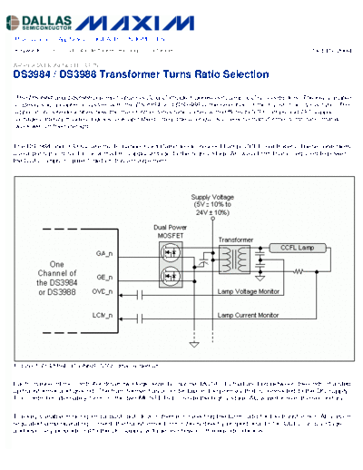
the CCFL lamps. Figure 1 details this arrangement.


Figure 1. DS3984 / DS3988 CCFL drive schematic.


Each channel of the controller drives two logic-level N-channel MOSFETs that are tied between the ends of a step-
up transformer and ground. The transformer has a center tap on the primary that is connected to the DC supply.
The controller alternately turns on the two MOSFETs to create the high voltage AC waveform on the secondary.


The key variable in designing a push-pull drive scheme is selecting the turns ratio for the transformer. At a given
regulated lamp operating current, the transformer turns ratio is directly proportional to the CCFL lamp voltage
and inversely proportional to the DC supply voltage as shown in the equation below.
For a given DC supply voltage, higher operating voltage CCFL lamps require a higher transformer turns ratio. For
a particular CCFL lamp, a higher DC supply voltage will require a lower transformer turns ratio. The operating
voltage of CCFL lamps varies, based on a number of factors including lamp diameter and length. Lamps with
smaller diameters and longer lengths operate at higher voltages.


There is not an exact formula for calculating the transformer turns ratio. Table 1 lists some empirically derived
transformer turns ratio for a variety of CCFL lamps. As can be seen from the table, the transformer turns ratio
decreases as the DC supply voltage increases, and the transformer turns ratio decreases as the operating voltage
of the CCFL lamps decreases.


Table 1. Target Transformer Turns Ratios for Various CCFL Lamps


                Lamp 1          Lamp 2          Lamp 3
Nominal DC
                2.4mm x 438mm 2.2mm x 258mm 2.0mm x 218mm
Supply Voltage2
                830 ~ 890 Vrms1 540 ~ 600 Vrms1 440 ~ 490 Vrms1
5V                 80:1                70:1                65:1
6V                 75:1                65:1                60:1
7V                 70:1                60:1                55:1
8V                 65:1                65:1                50:1
9V                 60:1                50:1                45:1
10V                55:1                45:1                40:1
11V                50:1                40:1                36:1
12V                45:1                36:1                32:1
13V                40:1                32:1                30:1
14V                38:1                30:1                28:1
15V                36:1                28:1                26:1
16V                34:1                26:1                25:1
17V                32:1                25:1                24:1
18V                30:1                24:1                23:1
19V                29:1                23:1                22:1
20V                28:1                22:1                21:1
21V                27:1                21:1                20:1
22V                26:1                20:1                19:1
23V                25:1                19:1                18:1
24V                24:1                18:1                17:1

Notes: 1. Lamp operating voltage at 5mArms operating current.
2. Assumes
◦ Jabse Service Manual Search 2026 ◦ Jabse Pravopis ◦ onTap.bg ◦ Other service manual resources online : Fixya ◦ eServiceinfo