Service Manuals, User Guides, Schematic Diagrams or docs for : . Various SM scena DBX 160-161 Calibration Procedure
<< Back | HomeMost service manuals and schematics are PDF files, so You will need Adobre Acrobat Reader to view : Acrobat Download Some of the files are DjVu format. Readers and resources available here : DjVu Resources
For the compressed files, most common are zip and rar. Please, extract files with Your favorite compression software ( WinZip, WinRAR ... ) before viewing. If a document has multiple parts, You should download all, before extracting.
Good luck. Repair on Your own risk. Make sure You know what You are doing.
Image preview - the first page of the document
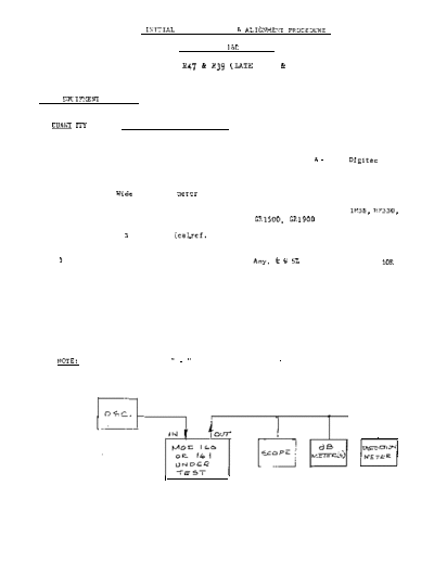
>> Download 160-161 Calibration Procedure documenatation <<
Text preview - extract from the document
                               ISITIAL FACTORY TEST 6 ALIGN?!ENT PROCEDL7RE

                                       DBX MODELS lb0 AND 161

                             WITHOUT Ii47 & R39 (LATE 160 & 161)


TEST EQUIWENT REQUIRED:


  QU_41\T l7-Y               ITEM                           TYPE OR EQUIVALENT

     1                  Signal Oscillator                 Kron-Hite 4200, Heath 1272

     1                  Digital Multimeter                Dana 3300, B & K 282, Digitec 2110

     1                  Oscilloscope                      Any (covering audio band)

    1                 . Wide Range db Deter               DBX SK-C-1026, HP 427

    1                  Harmonic distortion meter          DBX SK-B-1070, Heath lM58, HP330,
                                                          GR1500, CR1900

    1                  + 3 db meter (cal_ref. 1 volt)     DBX SKC-1071
                      (optional)

    1                 Resistor Substitution Box           Any. k w 57. values, typically 10K
                                                          to 4 7 0 K


   NOTE:         On model 160, tie It - II    terminals to Gnd, for normal testing.


                                                                         Revised 4-70-77
                                                                         350325-03
                            DBX MODELS 160 - 161

                            INITIAL TEST OUTLINE


SEQUENCE OF STEPS:

 1) Supply Trim

 2) RMS Trim

 3) VCA & RMS Symmetry

 4) Level Calibration

 5) Threshold Calibration

 6) Gain Change & input zero calibration

 7) Output Calibration

 8) Input Tracking

 g) Compression Circuit Calibration

10) (R78) Correct Value Test

11) Clipping

12) Response

13) Signal Clamping (Model 160 only)

14) Noise

15) Seal Pots

16) Burn-in

                                       .


                                                   350025-03
                                                                               P-3 .
                            160/161 INITIAL PROCEDURE


Before applying power to unit, check mechanical zero of meter.

     1) Supply Trim: Put resistance substitution box across R14 and measure DC
        voltage at (+) side of C7. Turn sub box until voltage is +15 volts
        + 50 MV (+14.950 to + 15.050). Solder appropriate resistor in
        place. Check (-) side of C8 to verify that it is -15 volts - 200 MV
                                                                    +
         (-14.800 to -15.200)

     2)    RMS Trim: (205) Connect sub box across the two RMS trim pins, and measure
           the offset at the input pin of the RMS module. Trim the sub box until
           voltage is zero + 15 MV, and solder appropriate resistor in place.
                           -
    274)   (209) With input of 1.228 VRMS at 100 Hz, place sub box between + v and
           the trim pin on the RMS module. Drop input level to - 60 db and adjust
           sub box until a symmetrical waveform is observed on camp pin, insert
           value chosen in R36 spot (typ 8K to 75KR)

     3) VCA & RMS Symmetry:
        Set oscillator to 1.228 VRMS
             a) 100 Hz (Tune for peak on distortion meter) Set front panel
                compression knob to "3" and output gain to +20. Turn threshold
                control counter clockwise from "3~" until external db meter reads
                 "0" db. Turn trim pots R27 and R34 until distortion reads minimum.

     4) Level Calibration:
        Set oscillator to 1.228 VRMS
             a) 100Hz turn R63 until the voltage at the end of R79 (closest to
                the center of unit) is -.Oll VDC

     5) Threshold Calibration:
        Turn front panel "Threshold Control" until both led's are off. Loosen
        knob and position so that pointer indicates just past "1V" and retighten.
         (When both leds are off the input signal is at threshold level.) (See
        fig. 1.) Step the oscillator up and down in 10 db steps verifying that
        the threshold level matches the input signal at successive calibration
        marks on the threshold dial.


                            ,03


                                                                   350025-03
                                                                                 P4


6.   GAIN CHANGE AND INPUT ZERO CALIBRATION
     6.1 Set oscillator to 100 Hz at 1.228VRMS.
     6.2 Set "THRESHOLD" fully Cw.                                                     /7
     6.3 Set "COMPRESSION" fully CCW.
     6.4 Place "METER" switch to "GAIN CHANGE" and adjust R51 for precisely "0"
         on the DBX 160/161 meter.
     6.5 Place "METER" switch to "INPUT" and adjust rear panel pot R62 for precisely
         "0" on the DBX 160/161 meter.
     6.6 Repeat steps 6.4 and 6.5.

7. OUTPUT CALIBRATION
   7.1 Place "MBTER" switch to "OUTPUT" and adjust the "OUTPUT GAIN" control for
       precisely "0" on the DBX 160/161 meter. If necessary adjust the knob on
       the "OUTPUT GAIN" control so that it points precisely to "0" on the front
       overlay at the same time that the DBX 160/161 meter reads precisely "0".
   7.2 With the requirements of step 7.1 met, the external DB meter should read
       "O+~lDB.

8. INPUT TRACKING
   8.1 Place "METER" switch to "INPUT and step oscillator to -3ODB.    Adjust R56
       for a reading of precisely -30 on the DBX 160/161 meter.

9. COMPRESSION CIRCUIT CALIBRATION
   9.1 Set "THRBSHOLD" fully CCW.
   9.2 Set "COMPRESSION" fully CW.
   9.3 Place "METER" switch to "OUTPUT"
   9.4 Step oscillator to -4ODB, and adjust the "OUTPUT GAIN" control for a
       convenient reading on the external DB meter.   (E.G. -4ODB). Step the
       oscillator to +lODB. The change on the External DB meter must be less
                                                                                       j--Y
       than 22DB.
   9.5 Adjust the "OUTPUT GAIN" control for a convenient reading on the DBX
       160/161 meter.   (E.G. -3ODB). Step the oscillator to -4ODB. The change
       on the DBX 160/161 meter should be less than +1DB.   Trim R58 with RlO2
       to obtain this reading.    (150K Nominal)
   9.6 Set "COMPRESSION" to "4". Step oscillator to -3ODB. Adjust "OUTPUT
       GAIN" control for a convenient reading on the External DB meter.
       (E.G. -3ODB) Step oscillator to +lODB.    The External DB meter should
       read -2ODB. Adjust R43 to obtain this reading. If necessary change R41
       (7.5K) to 10K (Recheck if R43 is adjusted1

     lo. (~78) CORRECT VALUB TEST
         10.1 Set "THRESHOLD" control fully CW.
         10.2 Apply 1OOHz at 1.228VRMS
         10.3 Set "OUTPUT GAIN" control for a reading of "0"DB on the External
              +3DB meter.
         10.4 Vary the "COMPRESSION" control from fully CCW to fully CW while
              watching the External DB meter. The change on the External DB
              meter must be less than +2DB.
                                                                          P5


11) Clipping:
    Step oscillator to + 1Odb and rotate compression control fully CCW. Turn
    output gain up until clipping is observed on the scope. Clipping should be
    clean and should occur well after + 20 dbm output for 160 and at +18 dbm
    for 161.

12) Response:
    Vary the frequency of the oscillator with Odb output, and verify that the
    output of the unit is constant + 1 db from 30 hz to 20 KHZ.

13) Signal Clamping (Model 160 only)
    For 160's turn power on and off, observing scope to check that the output
    does not contain a transient larger than the signal. After power is switched
    on the output should climb to normal, smoothly, in about a second.

14) Noise:
    Short input terminals and observe noise output of unit.    With covers on,
    noise should read less than -80 dbm.

15) Seal pots with wax (all except R62).

16) Burn-in:
    Place in burn-in rack with appropriate power applied.     (120 or 240 volts).
◦ Jabse Service Manual Search 2026 ◦ Jabse Pravopis ◦ onTap.bg ◦ Other service manual resources online : Fixya ◦ eServiceinfo