Service Manuals, User Guides, Schematic Diagrams or docs for : 3M 84-9801-5636-4_HCD-75_User_Manual_Feb83
<< Back | HomeMost service manuals and schematics are PDF files, so You will need Adobre Acrobat Reader to view : Acrobat Download Some of the files are DjVu format. Readers and resources available here : DjVu Resources
For the compressed files, most common are zip and rar. Please, extract files with Your favorite compression software ( WinZip, WinRAR ... ) before viewing. If a document has multiple parts, You should download all, before extracting.
Good luck. Repair on Your own risk. Make sure You know what You are doing.
Image preview - the first page of the document
>> Download 84-9801-5636-4_HCD-75_User_Manual_Feb83 documenatation <<
Text preview - extract from the document
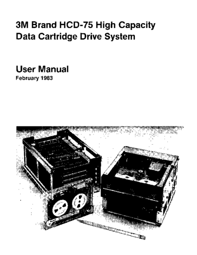
3M Brand HCD-75 High Capacity
Data Cartridge Drive System


User Manual
February 1983
                                                                  CONTENTS
Overview . . . . . . . . . . . . . . . . . . . . . . . . . . . . . . . .        Data Controls . . . . . . . . . . . . . . . . . . . . . . . . . . . . 39
Documentation . . . . . . . . . . . . . . . . . . ........ .                      Data Verification and Bad Block Table . . . . . . . . . . 39
                                                                                  Skip Table . . . . . . . . . . . . . . . . . . . . . . . . . . . . . 39
General Description . . . . . . . . . . . . . . . . . . . . . . . .        3      Tape Segmenting . . . . . . . . . . . . . . . . . . . . . . . . 44
DC600HC Data Cartridge ......................                              3      Addressing . . . . . . . . . . . . . . . . . . . . . . . . . . . . 45
HCD-75 Drive Module ........................                               3
HCD-75 Controller Module . . . . . . . . . . . . . . . . . . . .           4    Drive Module . . . . . . . . . . . . . . . . . . . . . . . . . . . . . 47
  Write Operations . . . . . . . . . . . . . . . . . . . . . . . .         5    Selecting Drive Addresses . . . . . . . . . . . . . . . . . . . . . 47
   Read Operations. . . . . . . . . . . . . . . . . . . . . . . ..         6    Drive Indicators . . . . . . . . . . . . . . . . . . . . . . . . . . . 47
System Functions . . . . . . . . . . . . . . . . . . . . . . . . ..        6
  Self-Test . . . . . . . . . . . . . . . . . . . . . . . . . . . . ..     6    Serial Interface . . . . . . . . . . . . . . . . . . . . . . . . . . . . 49
  Data Verification . . . . . . . . . . . . . . . . . . . . . . ..         6    Data Terminal Interface Specifications . . . . . . . . . . . . 49
  Skip Table. . . . . . . . . . . . . . . . . . . . . . . . . . . ..       6    Interface Connections . . . . . . . . . . . . . . . . . . . . . . . 49
  Tape Segmenting . . . . . . . . . . . . . . . . . . . . . . . .          6    Interface Signals . . . . . . . . . . . . . . . . . . . . . . . . . . . 49
User Interface . . . . . . . . . . . . . . . . . . . . . . . . . . . .     6    Operating Instructions . . . . . . . . . . . . . . . . . . . . . . . 50
  Parallel Interface . . . . . . . . . . . . . . . . . . . . . . . .       6       General . . . . . . . . . . . . . . . . . . . . . . . . . . . . . . . 50
  Serial Interface. . . . . . . . . . . . . . . . . . . . . . . . ..       7       Commands . . . . . . . . . . . . . . . . . . . . . . ~ ..... 50
Auto-Load Sequence . . . . . . . . . . . . . . . . . . . . . . ..          7         1. Write Diagnostic Command: W . . . . . . . . . . . . 50
                                                                                    2. Standard Verify: V . . . . . . . . . . . . . . . . . . . . 51
DC600HC and DC61 SHC High Capacity Data                                                 Key Verification Option: . . . . . . . . . . . . . . . . 51
Cartridge Prerecorded Format . . . . . . . . . . . . . . . . . 9                    3. Special Verify (Stop on Error):* . . . . . . . . . . . 53
General Information . . . . . . . . . . . . . . . . . . . . . . .. 9                4. Certify Command: C . . . . . . . . . . . . . . . . . . . 53
Prerecorded Format . . . . . . . . . . . . . . . . . . . . . . . . 9                    Key Certification Option: . . . . . . . . . . . . . . . . 53
Cartridge "Sizing" . . . . . . . . . . . . . . . . . . . . . . . . . 9               5. Read: R . . . . . . . . . . . . . . . . . . . . . . . . . . . 53
Recorded Format . . . . . . . . . . . . . . . . . . . . . . . . . . 11               6. Memory: M . . . . . . . . . . . . . . . . . . . . . . . . 54
Error Correction . . . . . . . . . . . . . . . . . . . . . . . . . . . 13            7. Display Memory: D . . . . . . . . . . . . . . . . . . . 55
                                                                                     8. Unload Cartridge: U . . . . . . . . . . . . . . . . . . . 55
Parallel Interface Operation . . . . . . . . . . . . . . . . . . . 15                9. Status Request: T . . . . . . . . . . . . . . . . . . . . 55
General . . . . . . . . . . . . . . . . . . . . . . . . . . . . . . . . . 15       10. Fill Memory: F . . . . . . . . . . . . . . . . . . . . . . 55
Interface Logic . . . . . . . . . . . . . . . . . . . . . . . . . . . . 15         11. Transfer Memory: X ................... 55
Interface Signals . . . . . . . . . . . . . . . . . . . . . . . . . . . 15         12. End: S . . . . . . . . . . . . . . . . . . . . . . . . . . . . 56
Initialize . . . . . . . . . . . . . . . . . . . . . . . . . . . . . . . . 16           Controller Status: . . . . . . . . . . . . . . . . . . . . . 56
Data Transfers . . . . . . . . . . . . . . . . . . . . . . . . . . . . 16
Data Line Options for Various Cabling Connections ... 18                        Memory Locations of Interest . . . . . . . . . . . . . . . . . . 57
    16-Bit Unidirectional . . . . . . . . . . . . . . . . . . . . . . 18
    16-Bit Bidirectional . . . . . . . . . . . . . . . . . . . . . . . 19       User Options . . . . . . . . . . . . . . . . . . . . . . . . . . . . . 61
   8-Bit Unidirectional . . . . . . . . . . . . . . . . . . . . . . 20          Variable Block Size . . . . . . . . . . . . . . . . . . . . . . . . . 61
   8-Bit Bidirectional . . . . . . . . . . . . . . . . . . . . . . . 22
Command Transfer . . . . . . . . . . . . . . . . . . . . . . , .. 24            Installation and Checkout . . . . . . . . . . . . . . . . . . . . 63
Block Timing . . . . . . . . . . . . . . . . . . . . . . . . . . . . . 26       Packaging . . . . . . . . . . . . . . . . . . . . . . . . . . . . . . . 63
Commands . . . . . . . . . . . . . . . . . . . . . . . . . . . . . . 27            Requirements . . . . . . . . . . . . . . . . . . . . . . . . . . 63
Write Data Transfers . . . . . . . . . . . . . . . . . . . . . . . . 28         Checkout . . . . . . . . . . . . . . . . . . . . . . . . . . . . . . . 63
Read Data Transfers . . . . . . . . . . . . . . . . . . . . . . . . 30          Power Requirements . . . . . . . . . . . . . . . . . . . . . . . . 64
Status Transfers . . . . . . . . . . . . . . . . . . . . . . . . . . . 31          Power Cables . . . . . . . . . . . . . . . . . . . . . . . . . . . 64
   I. System Status Word (First Word) . . . . . . . . . . . . 32                   Interconnect Cables . . . . . . . . . . . . . . . . . . . . . . 64
    II. Drive Status Word (Second Word) . . . . . . . . . . . 34                Cable Kit . . . . . . . . . . . . . . . . . . . . . . . . . . . . . . . 64
         Operational Status . . . . . . . . . . . . . . . . . . . . . 34        Dimensions . . . . . . . . . . . . . . . . . . . . . . . . . . . . . . 68
         Failure Status (Second Word) . . . . . . . . . . . . . . 36
    III. Current Track and Block Word (Third Word) ... 37
System Specifications ..... . . . . . . . . . . . . . . . . . . 69            Hen Environmental Test Results . . . . . . . . . . . . . . . . 71
   Mechanical Specification . . . . . . . . . . . . . . . . . . . 69            Shock and Vibration . . . . . . . . . . . . . . . . . . . . . . 71
   Temperature and Humidity . . . . . . . . . . . . . . . . . 69                Altitude . . . . . . . . . . . . . . . . . . . . . . . . . . . . . . 71
   Power Requirements . . . . . . . . . . . . . . . . . . . . . . 69            Electromagnetic Interference . . . . . . . . . . . . . . . . 71
   Reliability . . . . . . . . . . . . . . . . . . . . . . . . . . . . . 70   Routine Maintenance . . . . . . . . . . . . . . . . . . . . . . . 72
  Maintenance Replacement Schedule . . . . . . . . . . . . 70                   Drive Module . . . . . . . . . . . . . . . . . . . . . . . . . . . 72
  Performance . . . . . . . . . . . . . . . . . . . . . . . . . . . 70
                                                    OVERVIEW
The 3M HCD-75 High Capacity Data Cartridge Drive System         DOCUMENTATION
is a 1/4" tape cartridge system that can be used to record
                                                                This document, the HCD-75 User Manual, is intended to
up to 67.1 megabytes of user data on the 3M Brand
                                                                provide the user with more detailed information than may
DC600HC Data Cartridge. The HCD-75 system consists of
                                                                be found in introductory marketing material. Although
three basic components-drive module, controller module,
                                                                this manual does include some introductory information
and data cartridge-that offer the flexibility to fulfill the
                                                                about the HCD-75 system, the information is presented as
user's specific requirements. The compact design of the
                                                                a part of the more detailed information that is needed to
system itself and the high density storage capability of the
                                                                operate HCD-75 system components.
magnetic tape help to save the user both space and expense
as compared with the one-half-inch tape systems.
                                                                The HCD-75 User Manual is structured in sections, each of
                                                                which covers system components in detail and describes
The system command structure for the HCD-75 is simple
and straightforward. The HCD-75 features parallel data          step-by-step procedures for operating an HCD-75 system.
input/output of 16-bit words (or optional 8-bit bytes).         Installation information and specifications are presented
The system's dual, 1024-byte: I/O buffers allow asyn-           in such a way as to allow the user to install and operate
chronous transfer at an average rate of approximately           a system without having to refer to other sources
35 KBYTES/SEC at 60 IPS or 17.5 KBYTES/SEC at 30 IPS.           of information.


Local control of all tape drive functions frees the host        The sections of this manual and their central topics are:
from:
◦ Jabse Service Manual Search 2026 ◦ Jabse Pravopis ◦ onTap.bg ◦ Other service manual resources online : Fixya ◦ eServiceinfo